Bluetooth BR/EDR Full-Duplex Data and Voice Communication with WLAN Interference
This model shows how to simulate full-duplex data and voice communication between Bluetooth® basic rate/enhanced data rate (BR/EDR) Central and Peripheral nodes by using Bluetooth® Toolbox.
Using this example, you can:
Create and configure a Bluetooth BR/EDR piconet with Central and Peripheral nodes.
Simulate data and voice transmission through full-duplex communication mode. The supported data packet type is DM1, and the supported voice packets are HV1, HV2, HV3, and EV3.
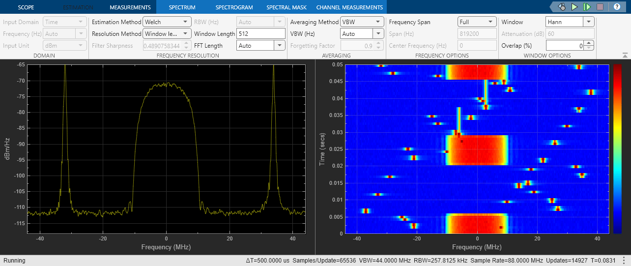
Visualize the power spectral density of Bluetooth BR/EDR waveforms in the presence of wireless local area network (WLAN) interference and an additive white Gaussian noise (AWGN) channel.
Compute bit error rate (BER) and throughput of Bluetooth BR/EDR waveforms with and without WLAN interference.
The system parameters block configures the packet type, slot pair, and channel type. The example uses Stateflow® to implement the acknowledgment scheme for the data packets and the synchronous connection-oriented (SCO) receiver state machine.
Example Model
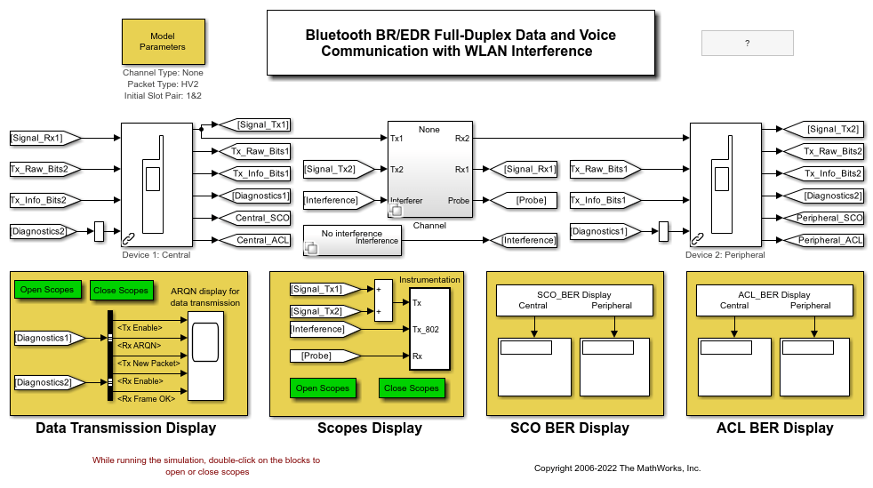
A Bluetooth core system consists of a radio frequency (RF) transceiver, baseband, and protocol stack. The system offers services that enable the connection of nodes and the exchange of a variety of classes of data between these nodes. This example model simulates a Bluetooth BR/EDR piconet consisting of a Central node, a Peripheral node, and a transmission channel.
Run the Simulink® Model.
modelname="BluetoothFullDuplexModel";
open_system(modelname)

This model includes a continuously variable slope delta-modulation (CVSD) speech coding, a header error check (HEC), a payload cyclic redundancy check (CRC) for DM1, a forward error correction (FEC), framing, Gaussian frequency-shift keying (GFSK) modulation, frequency hopping, a hop sequence generation, an 802.11b interferer, a wave file input/output (I/O), BER meters, a spectrum analyzer, a timing diagram, and a spectrogram plot.
You can set the system parameters by double-clicking the Model Parameters block in the top left. You can toggle instrumentation (spectrum, spectrogram, and timing diagram) on by double-clicking the Open Scopes and off by double clicking Close Scopes button. To turn the automatic repeat request number (ARQN) display for data transmission on or off, double click the same respective buttons in the Data Transmission Display section.
Model Description
The example models its blocks according to the Bluetooth Core Specifications 5.3 Vol 2 [ 2 ].
Transmitter
The transmitter consists of these subsystems.
Tx: Controller and Data Source— Enables audio if the device is sending a synchronous connection-oriented (SCO) packet. This subsystem also controls the generation and transmission of data packets if the device is sending an asynchronous connection-oriented (ACL) packet. The transmission of data packets is a function of the received ARQN signal in the previous slot.Tx: Payload FEC— Buffers and protects the data depending on the packet type. The output includes encoded payload bits and uncoded information bits to be used by BER meters in the receivers.Tx: Framing, HEC and Radio— Creates the packet header. The CRC protects the header and constructs it into frames. This subsystem also contains the General CRC Generator subsystem and the Radio subsystem.General CRC Generator— Transmits the data for CRC calculation.Radio— Modulates the signal with GFSK and upsamples it by 88 samples per symbol to 88 MHz. The transmission power is set to 1 mW. The radio subsystem contains continuous phase modulation, m-ary frequency shift keying block.CPM— The continuous phase modulation(CPM) baseband block implements the GFSK. The Bluetooth radio module uses GFSK, which represents a binary1as a positive frequency deviation and a binary0as a negative frequency deviation.79-FSK— The 79 frequency shift keying (FSK) baseband block implements frequency hopping in the Bluetooth radio. The Bluetooth radio accomplishes spectrum spreading by using 79 frequency hops, each displaced by 1 MHz, starting at 2.402 GHz and finishing at 2.480 GHz.
Receiver — The receiver contains an Rx: Radio, Controller and Deframe that consists of these subsystems.
Rx: Radio— Mixes the incoming signal from the current hop frequency. To accommodate the filter group delay, the subsystem filters the signal and moves it to a symbol boundary. It detects and extracts out the 366 frame bits (avoiding 1 symbol delay with selector parameters).Rx: Deframe and Decode— Segregates the incoming frame into access code, header, and payload. The subsystem then checks the access code, HEC, and CRC and performs the FEC decoding and ARQN extraction.Rx: Controller— Uses the Stateflow chart to decide whether the packet is successfully received by looking at the status of the ARQN bit. If the controller detects the ARQN bit as ACK, the Stateflow chart latches the payload and enables the BER meters. If the controller detects the ARQN bit as NACK, the packet fails and the Stateflow chart replaces the receiver bits with zeros.
Channel — The channel consists of these subsystems and blocks.
None— Specifies an ideal communication channel.AWGN— Adds AWGN.AWGN and 802.11b— Adds AWGN with 802.11b WLAN interference.
Free Space Path Loss block — Together with the
AWGNsubsystem and the802.11b Interferencesubsystem, shows the construction of a transmission channel.
Signals Between Central and Peripheral Nodes
Tx_Raw_Bits1 —The Central node randomly generates this signal from data and performs CRC and FEC encoding on the payload data. The Central node forms packets from the payload data according to the Bluetooth Core Specifications 5.2 [ 2 ]. (For the Peripheral node,Tx_Raw_Bits2performs the similar function).Signal_Tx1 —The Central node takesTx_Raw_Bits1and modulates it according to the Bluetooth standard.Signal_Tx1transmits through the channel (For the Peripheral node,Signal_Tx2performs the similar function).Signal_Rx1 —The Bluetooth Central node receives this raw signal after AWGN and 802.11b interference. The Central node demodulates and decodes this signal. (For the Peripheral node,Signal_Rx2performs the similar function).Tx_Info_Bits1 —The Central node generates the information data with a CRC payload but no FEC. The Peripheral node useTx_Info_Bits1for an SCO BER check on the Peripheral node. (For the Peripheral node,Tx_Info_Bits2performs the similar function).Diagnostics2 —The Central node uses a collection of frame and packet information for the ACL BER check. (For the Peripheral node,Diagnostics1performs the similar function).Central_SCO —The Central node provides SCO BER information for display (For the Peripheral node,Peripheral_SCOperforms the similar function).Central_ACL —This signal contains ACL BER information from the Central node for display (For the Peripheral node,Peripheral_ACLperforms the similar function).Interference —The 802.11b WLAN node generates the interference signal.
The Transmitter and Receiver sections use Stateflow® charts to implement their controllers.
Simulation and Results
Set the channel type as "None", "AWGN", or "AWGN and 802.11b". To specify the 802.11b WLAN interference with presence of AWGN, set the channel type to "AWGN and 802.11b".
set_param(modelname + "/Model Parameters",channel_type="AWGN and 802.11b");
Specify the type of Bluetooth BR/EDR data or voice packet type as "DM1", "HV1", "HV2", "HV3", or "EV3".
set_param(modelname + "/Model Parameters",packet_type="HV2");
Specify the slot pair as "1&2", "3&4", or "5&6".
set_param(modelname + "/Model Parameters",slot_pair="1&2");
Configure the simulation stop time in seconds.
set_param(modelname,StopTime="2.7");
Close Instrumentation to speed up the simulation.
timing = modelname + "/Instrumentation/Subsystem/Timing Diagram";
spectrum = modelname + "/Instrumentation/Subsystem/Spectrum Analyzer";
close_system(timing);
close_system(spectrum);
Set simulation time in seconds.
Tsim = 0.0837;
Start the simulation.
sim(modelname,Tsim);
Results and Displays
The simulation displays these plots —
Timing diagram — This plot shows the timing diagram of the received signal. You can visualize the timing diagram for the slots as well as the transmitted waveforms from the Bluetooth devices and interference from the 802.11b WLAN device.
open_system(timing)

Spectrum Analyzer — This plot shows the spectrum and the spectrogram of the received signal in the channel. The spectrogram, on the right side, shows the short-time Fourier transform of the combined waveform. The spectrogram, on the left side computes the instantaneous amplitude of the same waveform.
close_system(timing)
open_system(spectrum)

Compute BER
At the end of the simulation, The Central and Peripheral BER meters calculate the BER of the transmitted data.
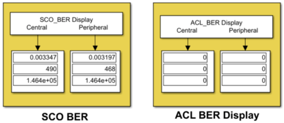
For example, the model generates this BER meter if you run the simulation with this configuration.
Simulation time — 1 second
Channel type —
"AWGN and 802.11b"Packet type —
"HV2"Slot pair —
"1&2"

For packet type "HV1", "HV2", "HV3", and "EV3", the simulation is successful if these conditions are satisfied.
ACL_BER_Displayvalues must be zero.SCO_BER_Displayvalues must be within the values specified by the Bluetooth Core Specifications [ 2 ].
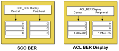
Similarly, the model generates this BER meter if you simulate the model with this configuration.
Simulation time — 1 second
Channel type —
"AWGN and 802.11b"Packet type —
"DM1"Slot pair —
"1&2"

For packet type "DM1", the simulation is successful if is satisfies these conditions.
SCO_BER_Displayvalues must be zero.ACL_BER_Displayvalues must be within the values specified by the Bluetooth Core Specifications [ 2 ].
Selected Bibliography
"Bluetooth® Technology Website - The Official Website for the Bluetooth Wireless Technology. Get up to Date Specifications, News, and Development Info." Accessed December 26, 2022. https://www.bluetooth.com/.
"Core Specification - Bluetooth® Technology Website." Accessed December 26, 2022. https://www.bluetooth.com/specifications/specs/core-specification-5-3/.