iqimbal
Apply I/Q imbalance to input signal
Description
Examples
Apply Amplitude Imbalance to 16-QAM
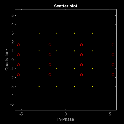
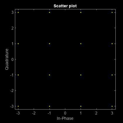
Generate a 16-QAM signal. Display the scatter plot.
x = qammod(randi([0 15],1000,1),16);
h = scatterplot(x);
hold on
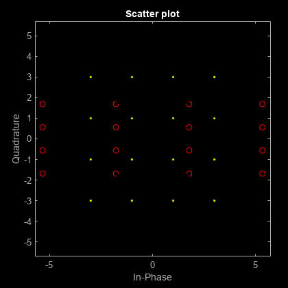
Apply a 10 dB amplitude imbalance. A positive amplitude imbalance causes horizontal stretching of the constellation.
y = iqimbal(x,10);
scatterplot(y,1,0,'ro',h)
Apply a -10 dB amplitude imbalance. A negative amplitude imbalance causes vertical stretching of the constellation.
z = iqimbal(x,-10); scatterplot(z,1,0,'k*',h) hold off
Apply Phase and Amplitude Imbalance to 16-QAM Signal
Generate a 16-QAM signal having two channels.
x = qammod(randi([0 15],1000,2),16);
Apply a 3 dB amplitude imbalance and a 10 degree phase imbalance to the first channel. Apply a –5 dB amplitude imbalance and a –15 degree phase imbalance to the second channel.
y = iqimbal(x,[3 -5],[10 -15]);
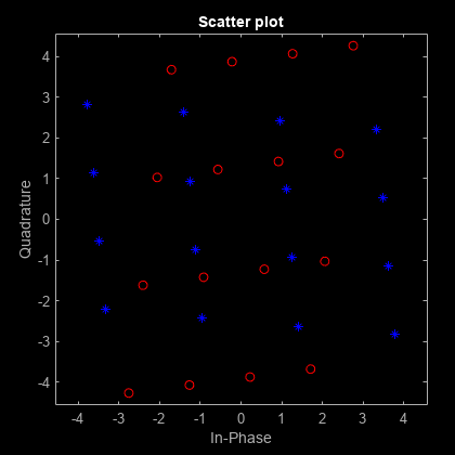
Plot the constellation diagram of both channels of the impaired signal.
h = scatterplot(y(:,1),1,0,'b*'); hold on scatterplot(y(:,2),1,0,'ro',h) hold off
The first channel is stretched horizontally, and the second channel is stretched vertically.
Apply I/Q Imbalance and DC Offset to QPSK
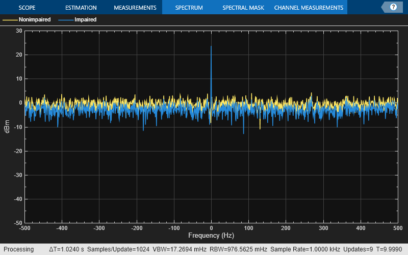
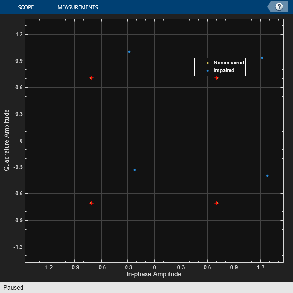
Apply a 1 dB, 5 degree I/Q imbalance to a QPSK signal. Then apply a DC offset. Visualize the offset using a spectrum analyzer.
Generate a QPSK sequence.
x = pskmod(randi([0 3],1e4,1),4,pi/4);
Apply a 1 dB amplitude imbalance and 5 degree phase imbalance to a QPSK signal. Apply a 0.5 + 0.3i DC offset.
y = iqimbal(x,1,5); z = y + complex(0.5,0.3);
Plot the spectrum of the nonimpaired and impaired signals.
sa = spectrumAnalyzer( ... SampleRate=1000, ... ChannelNames=["Nonimpaired","Impaired"], ... YLimits=[-50 30]); sa(x,z)
Display the corresponding scatter plot to see the effect of the I/Q imbalance and the DC offset.
cd = comm.ConstellationDiagram( ... NumInputPorts=2, ... ChannelNames=["Nonimpaired","Impaired"]); cd(x,z)
Correct I/Q Imbalance on Noisy 8-PSK Signal
Generate random data and apply 8-PSK modulation.
data = randi([0 7],2000,1); txSig = pskmod(data,8,pi/8);
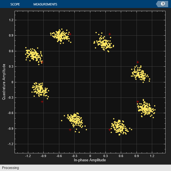
Pass the transmitted signal through an AWGN channel. Apply an I/Q imbalance.
noisySig = awgn(txSig,20); rxSig = iqimbal(noisySig,2,20);
Create a constellation diagram object that displays only the last 1000 symbols. Plot the constellation diagram of the impaired signal.
cd = comm.ConstellationDiagram('ReferenceConstellation',pskmod(0:7,8,pi/8), ... 'SymbolsToDisplaySource','Property','SymbolsToDisplay',1000); cd(rxSig)
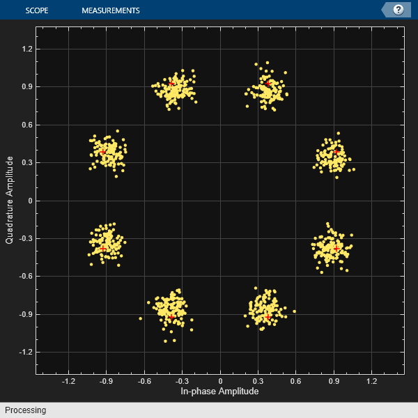
Correct for the I/Q imbalance by using a comm.IQImbalanceCompensator
object. Plot the constellation diagram of the signal after compensation.
iqComp = comm.IQImbalanceCompensator('StepSize',1e-3);
compSig = iqComp(rxSig);
cd(compSig)
The compensator removes the I/Q imbalance.
Input Arguments
x
— Input signal
column vector | matrix
Input signal, specified as a column vector or matrix. The function supports multichannel operations, where the number of columns corresponds to the number of channels.
Example: pskmod(randi([0 3],100,1),4,pi/4)
Data Types: single
| double
Complex Number Support: Yes
A
— Amplitude imbalance
real scalar | row vector
Amplitude imbalance in dB, specified as a real scalar or row vector.
If
A
is a scalar, the function applies the same amplitude imbalance to each channel.If
A
is a vector, then each element specifies the amplitude imbalance that is applied to the corresponding column (channel) of the input signal. The number of elements inA
must equal the number of columns inx
.
Example: 3
Example: [0
5]
Data Types: single
| double
P
— Phase imbalance
0
(default) | real scalar | row vector
Phase imbalance in degrees, specified as a real scalar or row vector.
If
P
is omitted, a phase imbalance of zero degrees is used.If
P
is a scalar, the function applies the same phase imbalance to each channel.If
P
is a vector, then each element specifies the phase imbalance that is applied to the corresponding column (channel) of the input signal. The number of elements inP
must equal the number of columns inx
.
Example: 10
Example: [2.5
7]
Data Types: single
| double
Output Arguments
y
— Output signal
vector | matrix
Output signal, returned as a vector or matrix having the same
dimensions as x
. The number of columns in y
corresponds
to the number of channels.
Data Types: single
| double
Complex Number Support: Yes
Algorithms
The iqimbal
function applies
an I/Q amplitude and phase imbalance to an input signal.
Given amplitude imbalance Ia in dB, the gain, g, resulting from the imbalance is defined as
Applying the I/Q imbalance to input signal x results in output signal y such that
where g is the imbalance gain and Ip is the phase imbalance in degrees.
Extended Capabilities
C/C++ Code Generation
Generate C and C++ code using MATLAB® Coder™.
Version History
Introduced in R2016b
See Also
iqcoef2imbal
| iqimbal2coef
| comm.IQImbalanceCompensator
| I/Q Imbalance
MATLAB Command
You clicked a link that corresponds to this MATLAB command:
Run the command by entering it in the MATLAB Command Window. Web browsers do not support MATLAB commands.
Select a Web Site
Choose a web site to get translated content where available and see local events and offers. Based on your location, we recommend that you select: .
You can also select a web site from the following list
How to Get Best Site Performance
Select the China site (in Chinese or English) for best site performance. Other MathWorks country sites are not optimized for visits from your location.
Americas
- América Latina (Español)
- Canada (English)
- United States (English)
Europe
- Belgium (English)
- Denmark (English)
- Deutschland (Deutsch)
- España (Español)
- Finland (English)
- France (Français)
- Ireland (English)
- Italia (Italiano)
- Luxembourg (English)
- Netherlands (English)
- Norway (English)
- Österreich (Deutsch)
- Portugal (English)
- Sweden (English)
- Switzerland
- United Kingdom (English)
Asia Pacific
- Australia (English)
- India (English)
- New Zealand (English)
- 中国
- 日本Japanese (日本語)
- 한국Korean (한국어)