End-to-End IEEE 802.15.4 PHY Simulation
This example shows how to generate waveforms, decode waveforms and compute BER curves for different PHY specifications of the IEEE® 802.15.4™ standard [ 1 ], using the Communications Toolbox™.
Background
The IEEE 802.15.4 standard specifies the PHY and MAC layers of low-rate wireless personal area networks (LR-WPANs) [1]. The IEEE 802.15.4 PHY and MAC layers provide the basis of other higher-layer standards, such as ZigBee, WirelessHart®, 6LoWPAN and MiWi. Such standards find application in home automation and sensor networking and are highly relevant to the Internet of Things (IoT) trend.
Physical Layer Implementations of IEEE 802.15.4
The original IEEE 802.15.4 standard and its amendments specify multiple PHY layers, which use different modulation schemes and support different data rates. These physical layers were devised for specific frequency bands and, to a certain extent, for specific countries. This example provides functions that generate and decode waveforms for the physical layers proposed in the original IEEE 802.15.4 specification (OQPSK in 2.4 GHz, BPSK in 868/915 MHz), IEEE 802.15.4b (OQPSK in 868/915 MHz), IEEE 802.15.4c (OQPSK in 780 MHz) and IEEE 802.15.4d (GFSK and BPSK in 950 MHz).
These physical layers specify a format for the PHY protocol data unit (PPDU) that includes a preamble, a start-of-frame delimiter (SFD), and the length and contents of the MAC protocol data unit (MPDU). The preamble and SFD are used for frame-level synchronization. In the following description, the term symbol denotes the integer index of a chip sequence (as per the IEEE 802.15.4 standard), not a modulation symbol such as a complex number.
OQPSK PHY: All OQPSK PHYs map every 4 PPDU bits to one symbol. The 2.4 GHz OQPSK PHY spreads each symbol to a 32-chip sequence, while the other OQPSK PHYs spread it to a 16-chip sequence. Then, the chip sequences are OQPSK modulated and passed to a half-sine pulse shaping filter (or a normal raised cosine filter, in the 780 MHz band). For a detailed description, see Clause 10 in [1].

BPSK PHY: The BPSK PHY differentially encodes the PPDU bits. Each resulting bit is spread to a 15-chip sequence. Then, the chip sequences are BPSK modulated and passed to a normal raised cosine filter. For a detailed description, see Clause 11 in [1].

GFSK PHY: The GFSK PHY first whitens the PPDU bits using modulo-2 addition with a PN9 sequence. The whitened bits are then GFSK modulated. For a detailed description, see Clause 15 in [1].

Waveform Generation, Decoding and BER Curve Calculation
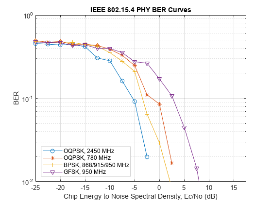
This code illustrates how to use the waveform generation and decoding functions for different frequency bands and compares the corresponding BER curves.
EcNo = -25:2.5:17.5;                % Ec/No range of BER curves
spc = 4;                            % samples per chip
msgLen = 8*120;                     % length in bits
s = rng(54806);                     % Seed random number generator
message = randi([0 1],msgLen,1);    % transmitted message

% Preallocate vectors to store BER results:
[berOQPSK2450, berOQPSK780, berBPSK, ...
    berGFSK] = deal(zeros(1,length(EcNo)));

% Create OQPSK configuration objects:
cfgOQPSK2450 = lrwpanOQPSKConfig(Band=2450, ...
  PSDULength=msgLen/8, SamplesPerChip=spc);
cfgOQPSK780  = lrwpanOQPSKConfig(Band=780, ... % or '868 MHz'/'915 MHz'
  PSDULength=msgLen/8, SamplesPerChip=spc);

for idx = 1:length(EcNo) % loop over the EcNo range

    % O-QPSK PHY, 2450 MHz
    waveform = lrwpanWaveformGenerator( ...
        message, cfgOQPSK2450);
    K = 2;      % information bits per symbol
    SNR = EcNo(idx) - 10*log10(spc) + 10*log10(K);
    received = awgn(waveform, SNR);
    bits     = lrwpan.PHYDecoderOQPSKNoSync( ...
        received,spc,'2450 MHz');
    [~, berOQPSK2450(idx)] = biterr(message, bits);

    % O-QPSK PHY, 780MHz
    waveform = lrwpanWaveformGenerator( ...
        message, cfgOQPSK780);
    SNR = EcNo(idx) - 10*log10(spc) + 10*log10(K);
    received = awgn(waveform, SNR);
    bits     = lrwpan.PHYDecoderOQPSKNoSync( ...
        received,spc,'780 MHz');
    [~, berOQPSK780(idx)] = biterr(message,bits);

    % BPSK PHY, 868/915/950 MHz
    waveform =  lrwpan.PHYGeneratorBPSK(message,spc);
    K = 1;      % information bits per symbol
    SNR = EcNo(idx) - 10*log10(spc) + 10*log10(K);
    received = awgn(waveform, SNR);
    bits     =  lrwpan.PHYDecoderBPSK(received,spc);
    [~, berBPSK(idx)] = biterr(message,bits);

    % GFSK PHY, 950 MHz
    waveform = lrwpan.PHYGeneratorGFSK(message,spc);
    K = 1;      % information bits per symbol
    SNR = EcNo(idx) - 10*log10(spc) + 10*log10(K);
    received = awgn(waveform, SNR);
    bits     =  lrwpan.PHYDecoderGFSK(received,spc);
    [~, berGFSK(idx)] = biterr(message, bits);
end

% plot BER curve
figure
semilogy(EcNo,berOQPSK2450,'-o',EcNo,berOQPSK780,'-*', ...
    EcNo,berBPSK,'-+',EcNo,berGFSK,'-v')
legend('OQPSK, 2450 MHz','OQPSK, 780 MHz', ...
    'BPSK, 868/915/950 MHz','GFSK, 950 MHz', ...
    'Location','southwest')
title('IEEE 802.15.4 PHY BER Curves')
xlabel('Chip Energy to Noise Spectral Density, Ec/No (dB)')
ylabel('BER')
axis([min(EcNo) max(EcNo) 10^-2 1])
grid on

Further Exploration
The example uses these features and undocumented utilities. The API and functionality of undocumented utilities may change in the future. To view the source code of the utilities, use the edit function.
lrwpanOQPSKConfig,lrwpanWaveformGenerator, andlrwpan.PHYDecoderOQPSKNoSync: Create and decode an IEEE 802.15.4 OQPSK waveformlrwpan.PHYGeneratorBPSKandlrwpan.PHYDecoderBPSK: Create and decode an IEEE 802.15.4 BPSK waveformlrwpan.PHYGeneratorGFSKandlrwpan.PHYDecoderGFSK: Create and decode an IEEE 802.15.4 GFSK waveform
References
1 - "IEEE Standard for Local and Metropolitan Area Networks--Part 15.4: Low-Rate Wireless Personal Area Networks (LR-WPANs)," in IEEE Std 802.15.4-2011 (Revision of IEEE Std 802.15.4-2006) , vol., no., pp.1-314, 5 Sept. 2011, doi: 10.1109/IEEESTD.2011.6012487.