End-to-End QAM Simulation with RF Impairments and Corrections
This example provides visualization capabilities to see the effects of RF impairments and corrections in a satellite downlink. The link employs 16-QAM modulation in the presence of AWGN and uses a High Power Amplifier (HPA) to overcome the losses associated with satellite communications. The HPA introduces nonlinear behavior that, when combined with other RF impairments, requires the use of mitigation techniques.
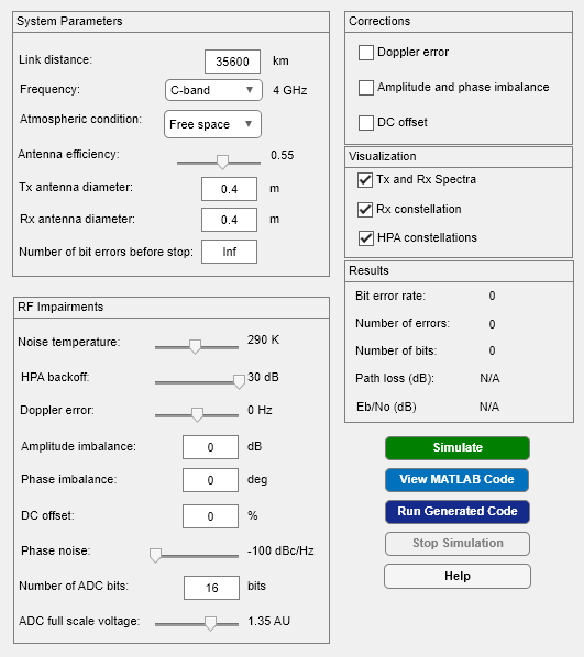
This example includes an app, QAMwithRFImpairmentsExample.mlapp and a MATLAB-based helper function, QAMwithRFImpairmentsSim.m, which receives its input parameters from the app.
Introduction
The simulation allows you to configure the parameters shown in the GUI.
Open the GUI to:
Modify the parameters
Run the simulation with MATLAB
Visualize signal constellations and spectra
View the underlying MATLAB code
Generate C code and run the simulation (with a valid MATLAB Coder™ license)
QAMwithRFImpairmentsExample

The Simulate button simulates the configured link using interpreted MATLAB code. While the simulation is running, you can modify some simulation parameters using the GUI. The impact of parameter setting updates is immediately observable on the Results panel or on the plots. Parameters that are nontunable while the simulation is running are grayed out. To modify nontunable parameters, the simulation must be stopped.
The View MATLAB Code button opens the simulator code in the editor allowing for visual inspection and further exploration of the underlying functions used in the simulation.
The Run Generated Code button compiles the MATLAB function into an executable MEX-file and runs the simulation once the compiling process is complete. The MEX version of the simulation runs much faster though there is a time penalty from the compiling process itself. You can modify the same parameters when running from either interpreted mode or from the MEX-file.
The Stop Simulation button stops the simulation during execution. This works for both interpreted MATLAB and the MEX-file. The button is active only when a simulation is running.
The Help button brings up this HTML page.
Simulation Overview
The simulation executes the following steps:
Generate random integers
Modulate with 16-QAM
Root raised cosine (RRC) transmit filter
Pass through an HPA
Apply transmit antenna gain
Apply path loss based on atmospheric condition
Pass the signal through an AWGN channel with RF impairments
Apply receive antenna gain
Remove DC offset
Apply automatic gain control
RRC receive filter
Apply ADC effects
Compensate for I/Q amplitude and phase imbalance
Correct for the Doppler shift
Demodulate 16-QAM
Calculate the bit error rate
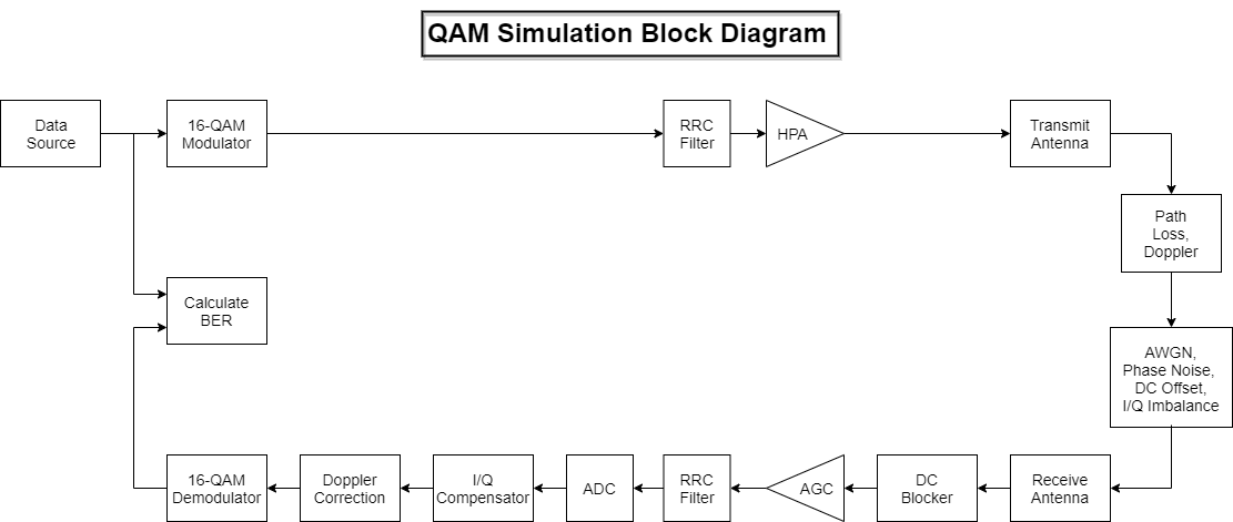
The following block diagram shows the architecture of the system.

You can specify the following signal impairments:
Receiver noise temperature in the range [0, 600] K
Doppler error in the range [-3, 3] Hz
DC offset, expressed as a percentage of the maximum signal voltage, in the range [0, 20]
Phase noise in the range [-100, -48] dBc/Hz
I/Q amplitude imbalance in the range [-5, 5] dB
I/Q phase imbalance in the range [-30, 30] degrees
HPA backoff level in the range [1, 30] dB
Quantization error by changing the number of ADC bits in the range of [2 16] bits
Saturation due to ADC full scale voltage in the range of [0.1 2] amplitude units (AUs)
An HPA backoff of 30 dB corresponds to negligible distortion because the amplifier is operating in its linear region, while 1 dB corresponds to severe distortion. A Saleh model is used to simulate the behavior of the HPA. Further information is available on the comm.MemorylessNonlinearity reference page.
The GUI provides the ability to enable or disable corrections for Doppler error, I/Q imbalance, and DC offset. These corrections are provided by three System objects. The comm.CarrierSynchronizer compensates for the frequency offset due to Doppler, the comm.IQImbalanceCompensator corrects the amplitude and phase imbalance, and the dsp.DCBlocker compensates for the DC offset.
Results and Displays
You can use GUI controls to display:
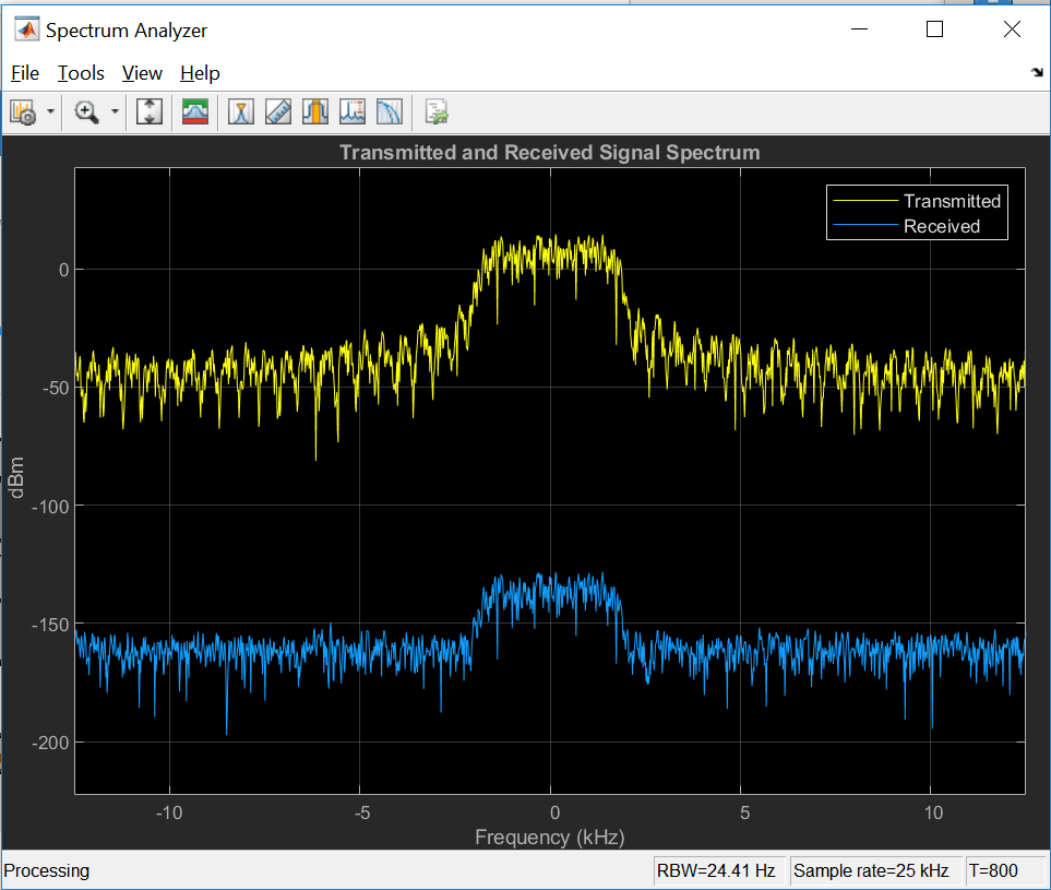
The spectrum of the transmitted signal measured at the output of the transmit RRC filter.
The spectrum of the received signal measured at the input of the receive RRC filter.
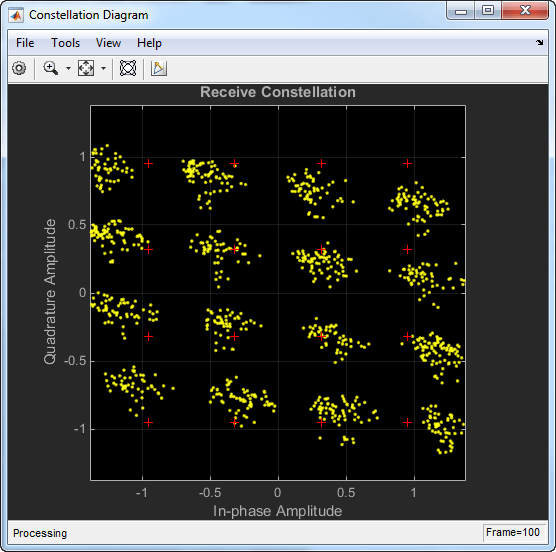
The constellation diagram of the received signal.
The constellation diagrams of the HPA input signal.
The constellation diagrams of the HPA output signal
A typical spectrum plot, using the default parameters, is shown. The effects of AWGN are most easily seen in the out-of-band signal spectrum, where the noise floor of the received signal is 20 dB higher than the transmitted signal spectrum. The received signal spectrum also shows the effect of propagation loss through the channel.

A plot of the constellation diagram is shown for the case in which the I/Q imbalance correction is disabled. The red + symbols denote the 16-QAM reference constellation. The constellation is scaled and rotated by the uncorrected imbalance.

The effects of nonlinear HPA behavior are shown as HPA Input and HPA Output using the same constellation diagram plot. The diagrams show the effects of AM/AM and AM/PM distortion when the amplifier operates 7 dB below saturation. AM/AM distortion causes the 'rounded' appearance of the HPA output signal constellation, while AM/PM causes the constellation to rotate.

The bit error rate, number of errors, total number of transmitted symbols, path loss, and the Eb/No are displayed directly on the results panel of the GUI.

Further Exploration
Use the GUI to change the parameters listed below.
Link gains and losses: Vary the noise temperature between 0 to 290 K (typical) to view the effects on the received signal spectrum analyzer plot. Likewise, change the link distance, atmospheric condition and carrier frequency to view the impact on the received signal spectrum. Changes in the link margin are also reflected in the calculated path loss and Eb/No.
HPA AM-to-AM and AM-to-PM conversion: Vary the HPA Backoff between 30 dB (negligible nonlinearity) to 1 dB (severe nonlinearity). A value of 7 dB corresponds to moderate nonlinearity. View the effects on the spectrum plot, the HPA output constellation, the received signal constellation diagram, and on the bit error rate. Increasing nonlinearity increases spectral regrowth and causes the HPA output constellation to become 'rounder' and rotate. The HPA Backoff parameter can be adjusted while the simulation is executing.
Phase noise: Set the Phase Noise to -48 dBc/Hz (high) and observe the increased variance in the tangential direction in the received signal constellation diagram. This level of phase noise is sufficient to cause errors in an otherwise error-free channel. Set the Phase Noise to -55 dBc/Hz (low) and observe that the variance in the tangential direction has decreased. This level of phase noise does not significantly increase the error rate. Now, set the HPA Backoff level parameter to 7 dB (moderate nonlinearity). Note that even though the moderate HPA nonlinearity and the moderate phase noise do not cause many bit errors when applied individually, they do cause significantly more bit errors when applied together. The Phase Noise parameter can be adjusted only when the simulation is stopped.
DC offset and DC offset correction: Set the DC offset to
10and disable the DC offset correction by unchecking the DC Offset checkbox. The constellation diagram changes significantly. Re-enable the DC Offset correction and view the received signal constellation diagram and signal spectrum to verify that the DC offset is removed. Both the DC offset and the DC offset correction parameters can be modified during simulation execution.I/Q imbalance: Disable the Amplitude and phase imbalance box to view the effects of an I/Q imbalance on the received constellation diagram. Modify the amplitude and phase imbalance fields to observe the effects of different values on the received signal constellation diagram. Re-enable the I/Q imbalance correction to verify that the receive constellation aligns with its reference points. These parameters can be modified during execution.
Doppler and Doppler compensation: Set Doppler error to 0.7 Hz and disable the Doppler error correction to show the effect of uncorrected Doppler on the received signal. Note that the BER is close to 0.5. Re-enable the Doppler error correction to correct for the Doppler error. Verify that the BER decreases. These parameters are available only when the simulation is stopped.
ADC Effects: Decrease the number of ADC bits to view the effect of increasing quantization errors on the received signal. Decrease the ADC full scale voltage to impose saturation on the received signal and view its effect on the system performance.
Code Generation: Run the simulation by clicking the Run Generated Code button. The first time this is done, the simulation compiles before executing, which makes the process take longer than it does when simulating with interpreted MATLAB. Change the HPA backoff level and rerun the simulation. Note that the results panel updates very quickly. Now, change the Phase noise and click the Run Generated Code button. The code is recompiled because the phase noise is a nontunable parameter. Enable the Rx constellation option and rerun the simulation. You can see that when the scope is activated, the bit error results accumulate more slowly but the scope updates much faster than it does when running with interpolated MATLAB.
BER estimation: By default, the Number of bit errors parameter is set to
Infso that the effects of the impairments and corrections can be easily visualized on the scopes. For BER estimation, it is typically sufficient to collect 50 to 200 errors; consequently, disable the scopes and change the Number of bit errors parameter fromInfto 100. It is important to leave the modifiable parameters unchanged when the simulation is running to obtain a valid BER estimate.
Selected Bibliography
[1] Saleh, Adel A.M., "Frequency-Independent and Frequency-Dependent Nonlinear Models of TWT Amplifiers," IEEE® Transactions on Communications, Vol. COM-29, No. 11, November 1981.
[2] Kasdin, N.J., "Discrete Simulation of Colored Noise and Stochastic Processes and 1/(f^alpha); Power Law Noise Generation," The Proceedings of the IEEE, Vol. 83, No. 5, May, 1995.
[3] Kasdin, N. Jeremy, and Todd Walter, "Discrete Simulation of Power Law Noise," 1992 IEEE Frequency Control Symposium.
[4] Sklar, Bernard, Digital Communications: Fundamentals and Applications, Englewood Cliffs, N.J., Prentice Hall, 1988.