Main Content

Eye Diagram Analysis

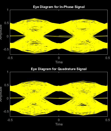
In digital communications, an eye diagram provides a visual indication of how noise might impact system performance.

Use the Eye Diagram block to examine the eye diagram of signals.

Note

Analysis such as measurements, histograms, and bathtub curves, will be removed from the Eye Diagram block in a future release.

For the new eye diagram block, see Eye Diagram.

You can obtain the following measurements on an eye diagram:

  • Amplitude Measurements

    • Eye Amplitude

    • Eye Crossing Amplitude

    • Eye Crossing Percentage

    • Eye Height

    • Eye Level

    • Eye SNR

    • Quality Factor

    • Vertical Eye Opening

  • Time Measurements

    • Deterministic Jitter

    • Eye Crossing Time

    • Eye Delay

    • Eye Fall Time

    • Eye Rise Time

    • Eye Width

    • Horizontal Eye Opening

    • Peak-to-Peak Jitter

    • Random Jitter

    • RMS Jitter

    • Total Jitter

Measurements assume that the eye diagram object has valid data. A valid eye diagram has two distinct eye crossing points and two distinct eye levels.

The deterministic jitter, horizontal eye opening, quality factor, random jitter, and vertical eye opening measurements utilize a dual-Dirac algorithm. Jitter is the deviation of a signal’s timing event from its intended (ideal) occurrence in time [1]. Jitter can be represented with a dual-Dirac model. A dual-Dirac model assumes that the jitter has two components: deterministic jitter (DJ) and random jitter (RJ). The DJ PDF comprises two delta functions, one at μL and one at μR. The RJ PDF is assumed to be Gaussian with zero mean and variance σ.

The Total Jitter (TJ) PDF is the convolution of these two PDFs, which is composed of two Gaussian curves with variance σ and mean values μL and μR.

The dual-Dirac model is described in [5] in more detail. The amplitude of the two Dirac functions may not be the same. In such a case, the analyze method estimates these amplitudes, ρL and ρR.

Amplitude Measurements

You can use the vertical histogram to obtain a variety of amplitude measurements. For complex signals, measurements are done on both in-phase and the quadrature components, unless otherwise specified.

Note

For amplitude measurements, at least one bin per vertical histogram must reach 10 hits before the measurement is taken, ensuring higher accuracy.

Eye Amplitude (EyeAmplitude)

Eye Amplitude, measured in Amplitude Units (AU), is defined as the distance between two neighboring eye levels. For an NRZ signal, there are only two levels: the high level (level 1 in figure) and the low level (level 0 in figure). The eye amplitude is the difference of these two values.

Eye Crossing Amplitude (EyeCrossingLevel)

Eye crossing amplitudes are the amplitude levels at which the eye crossings occur, measured in Amplitude Units (AU). The analyze method calculates this value using the mean value of the vertical histogram at the crossing times [3].

The next figure shows the vertical histogram at the first eye crossing time.

Eye Crossing Percentage (EyeOpeningVer)

Eye Crossing Percentage is the location of the eye crossing levels as a percentage of the eye amplitude.

Eye Height (EyeHeight)

Eye Height, measured in Amplitude Units (AU), is defined as the 3σ distance between two neighboring eye levels.

For an NRZ signal, there are only two levels: the high level (level 1 in figure) and the low level (level 0 in figure). The eye height is the difference of the two 3σ points. The 3σ point is defined as the point that is three standard deviations away from the mean value of a PDF.

Eye Level (EyeLevel)

Eye Level is the amplitude level used to represent data bits, measured in Amplitude Units (AU).

For an ideal NRZ signal, there are two eye levels: +A and –A. The analyze method calculates eye levels by estimating the mean value of the vertical histogram in a window around the EyeDelay, which is also the 50% point between eye crossing times [3]. The width of this window is determined by the EyeLevelBoundary property of the eye measurement setup object.

The analyze method calculates the mean value of all the vertical histograms within the eye level boundaries. The mean vertical histograms show two distinct PDFs, one for each eye level.

Eye SNR (EyeSNR)

Eye signal-to-noise ratio is defined as the ratio of the eye amplitude to the sum of the standard deviations of the two eye levels. It can be expressed as:

SNR = L1L0σ1+σ0


where L1 and L0 represent eye level 1 and 0, respectively, and σ1 and σ2 are the standard deviation of eye level 1 and 0, respectively.

For an NRZ signal, eye level 1 corresponds to the high level, and the eye level 0 corresponds to low level.

Quality Factor (QualityFactor)

The analyze method calculates Quality Factor the same way as the eye SNR. However, instead of using the mean and standard deviation values of the vertical histogram for L1 and σ1, the analyze method uses the mean and standard deviation values estimated using the dual-Dirac method. For more detail, see dual-Dirac section in [2].

Vertical Eye Opening (EyeOpeningVer)

Vertical Eye Opening is defined as the vertical distance between two points on the vertical histogram at EyeDelay that corresponds to the BER value defined by the BERThreshold property of the eye measurement setup object. The analyze method calculates this measurement taking into account the random and deterministic components using a dual-Dirac model [5] (see the Dual Dirac Section). A typical BER value for the eye opening measurements is 10-12, which approximately corresponds to the 7σ point assuming a Gaussian distribution.

Time Measurements

You can use the horizontal histogram of an eye diagram to obtain a variety of timing measurements.

Note

For time measurements, at least one bin per horizontal histogram must reach 10 hits before the measurement is taken.

Deterministic Jitter (JitterDeterministic)

Deterministic Jitter is the deterministic component of the jitter. You calculate it using the tail mean value, which is estimated using the dual-Dirac method as follows [5]:

DJ = μL — μR

where μL and μR are the mean values returned by the dual-Dirac algorithm.

Eye Crossing Time (EyeCrossingTime)

Eye crossing times are calculated as the mean of the horizontal histogram for each crossing point, around the reference amplitude level. This value is measured in seconds. The mean value of all the horizontal PDFs is calculated in a region defined by the CrossingBandWith property of the eye measurement setup object.

The region is from -Atotal* BW to +Atotal* BW, where Atotal is the total amplitude range of the eye diagram (i.e., A total = A maxAmin) and BW is the crossing band width.

Because this example assumes two symbols per trace, the average PDF in this region indicate there are two crossing points.

Note

When an eye crossing time measurement falls within the [-0.5/Fs, 0) seconds interval, the time measurement wraps to the end of the eye diagram, i.e., the measurement wraps by 2*Ts seconds (where Ts is the symbol time). For a complex signal case, the analyze method issues a warning if the crossing time measurement of the in-phase branch wraps while that of the quadrature branch does not (or vice versa).

To avoid the time-wrapping or a warning, add a half-symbol duration delay to the current value in the MeasurementDelay property of the eye diagram object. This additional delay repositions the eye in the approximate center of the scope.

Eye Delay (EyeDelay)

Eye Delay is the distance from the midpoint of the eye to the time origin, measured in seconds. The analyze method calculates this distance using the crossing time. For a symmetric signal, EyeDelay is also the best sampling point.

Eye Fall Time (EyeFallTime)

Eye Fall Time is the mean time between the high and low threshold values defined by the AmplitudeThreshold property of the eye measurement setup object. The fall time is calculated from 10% to 90% of the eye amplitude.

Eye Rise Time (EyeRiseTime)

Eye Rise Time is the mean time between the low and high threshold values defined by the AmplitudeThreshold property of the eye measurement setup object. The rise time is calculated from 10% to 90% of the eye amplitude.

Eye Width (EyeWidth)

Eye Width is the horizontal distance between two points that are three standard deviations (3σ ) from the mean eye crossing times, towards the center of the eye. The value for Eye Width measurements is seconds.

Horizontal Eye Opening (EyeOpeningHor)

Horizontal Eye Opening is the horizontal distance between two points on the horizontal histogram that correspond to the BER value defined by the BERThreshold property of the eye measurement setup object. The measurement is take at the amplitude value defined by the ReferenceAmplitude property of the eye measurement setup object. It is calculated taking into account the random and deterministic components using a dual-Dirac model [5] (see the Dual Dirac Section).

A typical BER value for the eye opening measurements is 10-12, which approximately corresponds to the 7σ point assuming a Gaussian distribution.

Peak-to-Peak Jitter (JitterP2P)

Peak-To-Peak Jitter is the difference between the extreme data points of the histogram.

Random Jitter (JitterRandom)

Random Jitter is defined as the Gaussian unbounded component of the jitter. The analyze method calculates it using the tail standard deviation estimated using the dual-Dirac method as follows [5]:

RJ = (QL + QR) * σ

where

QL=2*erfc1(2*BERρL)

and

QR=2*erfc1(2*BERρR)

BER is the bit error ratio at which the random jitter is calculated. It is defined with the BERThreshold property of the eye measurement setup object.

RMS Jitter (JitterRMS)

RMS Jitter is the standard deviation of the jitter calculated from the horizontal histogram.

Total Jitter (JitterTotal)

Total Jitter is the sum of the random jitter and the deterministic jitter [5].

References

[1] Nelson Ou, et al, Models for the Design and Test of Gbps-Speed Serial Interconnects,IEEE Design & Test of Computers, pp. 302-313, July-August 2004.

[2] HP E4543A Q Factor and Eye Contours Application Software, Operating Manual, http://agilent.com

[3] Agilent 71501D Eye-Diagram Analysis, User’s Guide, http://www.agilent.com

[4] 4] Guy Foster, Measurement Brief: Examining Sampling Scope Jitter Histograms, White Paper, SyntheSys Research, Inc., July 2005.

[5] Jitter Analysis: The dual-Dirac Model, RJ/DJ, and Q-Scale, White Paper, Agilent Technologies, December 2004, http://www.agilent.com

See Also