Hard- vs. Soft-Decision Demodulation Examples
Log-Likelihood Ratio (LLR) Demodulation
This example shows the BER performance improvement for QPSK modulation when using log-likelihood ratio (LLR) instead of hard-decision demodulation in a convolutionally coded communication link. With LLR demodulation, one can use the Viterbi decoder either in the unquantized decoding mode or the soft-decision decoding mode. Unquantized decoding, where the decoder inputs are real values, though better in terms of BER, is not practically viable. In the more practical soft-decision decoding, you quantize the demodulator output before sending it to the decoder. It is generally observed that soft-decision decoding does not incur a significant cost in BER while significantly reducing the decoder complexity. This example validates the BER performance through simulation.
For a Simulink™ version of this example, see LLR vs. Hard Decision Demodulation in Simulink.
Initialization
Initialize simulation parameters.
M = 4;               % Modulation order
bitsPerIter = 1.2e4; % Number of bits to simulate
EbNo = 3;            % Information bit Eb/No in dB
Initialize coding properties for a rate 1/2, constraint length 7 code.
codeRate = 1/2;          % Code rate of convolutional encoder
constLen = 7;            % Constraint length of encoder
codeGenPoly = [171 133]; % Code generator polynomial of encoder
tblen = 32;              % Traceback depth of Viterbi decoder
trellis = poly2trellis(constLen,codeGenPoly);
Create a comm.ConvolutionalEncoder System object™ by using trellis as an input.
enc = comm.ConvolutionalEncoder(trellis);
Channel
The signal going into the AWGN channel is the modulated encoded signal. To achieve the required noise level, adjust the Eb/No for coded bits and multi-bit symbols. Calculate the value based on the value you want to simulate.
SNR = convertSNR(EbNo,"ebno","BitsPerSymbol",log2(M),"CodingRate",codeRate);
Viterbi Decoding
Create comm.ViterbiDecoder objects to act as the hard-decision, unquantized, and soft-decision decoders. For all three decoders, set the traceback depth to tblen.
decHard = comm.ViterbiDecoder(trellis,'InputFormat','Hard', ...
    'TracebackDepth',tblen);

decUnquant = comm.ViterbiDecoder(trellis,'InputFormat','Unquantized', ...
    'TracebackDepth',tblen);

decSoft = comm.ViterbiDecoder(trellis,'InputFormat','Soft', ...
    'SoftInputWordLength',3,'TracebackDepth',tblen);
Calculating the Error Rate
Create comm.ErrorRate objects to compare the decoded bits to the original transmitted bits. The Viterbi decoder creates a delay in the decoded bit stream output equal to the traceback length. To account for this delay, set the ReceiveDelay property of the comm.ErrorRate objects to tblen.
errHard = comm.ErrorRate('ReceiveDelay',tblen);
errUnquant = comm.ErrorRate('ReceiveDelay',tblen);
errSoft = comm.ErrorRate('ReceiveDelay',tblen);
System Simulation
Generate bitsPerIter message bits. Then convolutionally encode and modulate the data.
txData = randi([0 1],bitsPerIter,1);
encData = enc(txData);
modData = pskmod(encData,M,pi/4,InputType="bit");
Pass the modulated signal through an AWGN channel.
[rxSig,nVar] = awgn(modData,SNR);
Before using a comm.ViterbiDecoder object in the soft-decision mode, the output of the demodulator needs to be quantized. This example uses a comm.ViterbiDecoder object with a SoftInputWordLength of 3. This value is a good compromise between short word lengths and a small BER penalty. Define partition points for 3-bit quantization.
demodLLR.Variance = nVar;
partitionPoints = (-1.5:0.5:1.5)/nVar;
Demodulate the received signal and output hard-decision bits.
hardData = pskdemod(rxSig,M,pi/4,OutputType="bit");Demodulate the received signal and output LLR values.
LLRData = pskdemod(rxSig,M,pi/4,OutputType="llr",NoiseVariance=nVar);Hard-decision decoding
Pass the demodulated data through the Viterbi decoder. Compute the error statistics.
rxDataHard = decHard(hardData);
berHard = errHard(txData,rxDataHard);
Unquantized decoding
Pass the demodulated data through the Viterbi decoder. Compute the error statistics.
rxDataUnquant = decUnquant(LLRData);
berUnquant = errUnquant(txData,rxDataUnquant);
Soft-decision decoding
Pass the demodulated data to the quantiz function. This data must be multiplied by -1 before being passed to the quantizer, because, in soft-decision mode, the Viterbi decoder assumes that positive numbers correspond to 1s and negative numbers to 0s. Pass the quantizer output to the Viterbi decoder. Compute the error statistics.
quantizedValue = quantiz(-LLRData,partitionPoints);
rxDataSoft = decSoft(double(quantizedValue));
berSoft = errSoft(txData,rxDataSoft);
Running Simulation Example
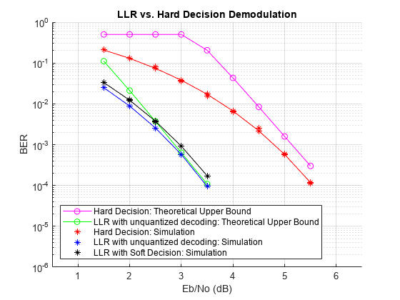
Simulate the previously described communications system over a range of Eb/No values by executing the simulation file simLLRvsHD. It plots BER results as they are generated. BER results for hard-decision demodulation and LLR demodulation with unquantized and soft-decision decoding are plotted in red, blue, and black, respectively. A comparison of simulation results with theoretical results is also shown. Observe that the BER is only slightly degraded by using soft-decision decoding instead of unquantized decoding. The gap between the BER curves for soft-decision decoding and the theoretical bound can be narrowed by increasing the number of quantizer levels.
This example may take some time to compute BER results. If you have the Parallel Computing Toolbox™ (PCT) installed, you can set usePCT to true to run the simulation in parallel. In this case, the file LLRvsHDwithPCT is run.
To obtain results over a larger range of Eb/No values, modify the appropriate supporting files. Note that you can obtain more statistically reliable results by collecting more errors.
usePCT = false;
if usePCT && license('checkout','Distrib_Computing_Toolbox') ...
        && ~isempty(ver('parallel'))
    LLRvsHDwithPCT(1.5:0.5:5.5,5);
else
    simLLRvsHD(1.5:0.5:5.5,5);
end
Appendix
The following functions are used in this example:
simLLRvsHD.m— Simulates system without PCT.LLRvsHDwithPCT.m— Simulates system with PCT.simLLRvsHDPCT.m— Helper function called by LLRvsHDwithPCT.
LLR vs. Hard Decision Demodulation in Simulink
This model shows the improvement in BER performance when using log-likelihood ratio (LLR) instead of hard decision demodulation in a convolutionally coded communication link.
For a MATLAB® version of this example, see Log-Likelihood Ratio (LLR) Demodulation.
System Setup
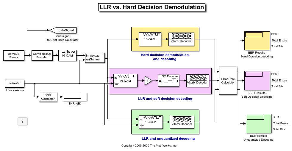
This example model simulates a convolutionally coded communication system having one transmitter, an AWGN channel and three receivers. The convolutional encoder has a code rate of 1/2. The system employs a 16-QAM modulation. The modulated signal passes through an additive white Gaussian noise channel. The top receiver performs hard decision demodulation in conjunction with a Viterbi decoder that is set up to perform hard decision decoding. The second receiver has the demodulator configured to compute log-likelihood ratios (LLRs) that are then quantized using a 3-bit quantizer. It is well known that the quantization levels are dependent on noise variance for optimum performance [2]. The exact boundaries of the quantizer are empirically determined here. A Viterbi decoder that is set up for soft decision decoding processes these quantized values. The LLR values computed by the demodulator are multiplied by -1 to map them to the right quantizer index for use with Viterbi Decoder. To compute the LLR, the demodulator must be given the variance of noise as seen at its input. The third receiver includes a demodulator that computes LLRs which are processed by a Viterbi decoder that is set up in unquantized mode. The BER performance of each receiver is computed and displayed.
modelName = 'commLLRvsHD';
open_system(modelName);
System Simulation and Visualization
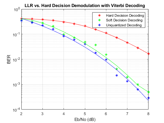
Simulate this system over a range of information bit Eb/No values. Adjust these Eb/No values for coded bits and multi-bit symbols to get noise variance values required for the AWGN block and Rectangular QAM Baseband Demodulator block. Collect BER results for each Eb/No value and visualize the results.
EbNo     = 2:0.5:8; % information rate Eb/No in dB
codeRate = 1/2;     % code rate of convolutional encoder
nBits    = 4;       % number of bits in a 16-QAM symbol
Pavg     = 10;      % average signal power of a 16-QAM modulated signal
snr      = EbNo - 10*log10(1/codeRate) + 10*log10(nBits); % SNR in dB
noiseVarVector = Pavg ./ (10.^(snr./10)); % noise variance

% Initialize variables for storing the BER results
ber_HD  = zeros(1,length(EbNo));
ber_SD  = zeros(1,length(EbNo));
ber_LLR = zeros(1, length(EbNo));

% Loop over all noiseVarVector values
for idx=1:length(noiseVarVector)
    noiseVar = noiseVarVector(idx); %#ok<NASGU>
    sim(modelName);
    % Collect BER results
    ber_HD(idx)  = BER_HD(1);
    ber_SD(idx)  = BER_SD(1);
    ber_LLR(idx) = BER_LLR(1);
end

% Perform curve fitting and plot the results
fitBER_HD  = real(berfit(EbNo,ber_HD));
fitBER_SD  = real(berfit(EbNo,ber_SD));
fitBER_LLR = real(berfit(EbNo,ber_LLR));
semilogy(EbNo,ber_HD,'r*', ...
    EbNo,ber_SD,'g*', ...
    EbNo,ber_LLR,'b*', ...
    EbNo,fitBER_HD,'r', ...
    EbNo,fitBER_SD,'g', ...
    EbNo,fitBER_LLR,'b');
legend('Hard Decision Decoding', ...
    'Soft Decision Decoding','Unquantized Decoding');
xlabel('Eb/No (dB)');
ylabel('BER');
title('LLR vs. Hard Decision Demodulation with Viterbi Decoding');
grid on;
To experiment with this system further, try different modulation types. This system uses a binary mapped modulation scheme for faster error collection but it is well known that Gray mapped signal constellation provides better BER performance. Experiment with various constellation ordering options in the modulator and demodulator blocks. Configure the demodulator block to compute approximate LLR to see the difference in the BER performance compared to hard decision demodulation and LLR. Try out a different range of Eb/No values. Finally, investigate different quantizer boundaries for your modulation scheme and Eb/No values.
Using Dataflow in Simulink
You can configure this example to use data-driven execution by setting the Domain parameter to dataflow for Dataflow Subsystem. With dataflow, blocks inside the domain, execute based on the availability of data as rather than the sample timing in Simulink®. Simulink automatically partitions the system into concurrent threads. This autopartitioning accelerates simulation and increases data throughput. To learn more about dataflow and how to run this example using multiple threads, see Multicore Simulation of Comparing Demodulation Types.
% Cleanup
close_system(modelName,0);
clear modelName EbNo codeRate nBits Pavg snr noiseVarVector ...
    ber_HD ber_SD ber_LLR idx noiseVar fitBER_HD fitBER_SD fitBER_LLR;
Selected Bibliography
[1] J. L. Massey, "Coding and Modulation in Digital Communications", Proc. Int. Zurich Seminar on Digital Communications, 1974
[2] J. A. Heller, I. M. Jacobs, "Viterbi Decoding for Satellite and Space Communication", IEEE® Trans. Comm. Tech. vol COM-19, October 1971