UWB Localization Using IEEE 802.15.4z
This example shows how to estimate the location of a single device as per the IEEE® 802.15.4z™ standard [ 2 ].
Overview
The IEEE 802.15.4z amendment [ 2 ] of the IEEE® 802.15.4 standard [ 1 ] is a MAC and PHY specification designed for ranging and localization using ultra-wideband (UWB) communication. The very short pulse durations of UWB allow a finer granularity in the time domain and therefore more accurate estimates in the spatial domain.
The key ranging and localization functionality of the 802.15.4z amendment includes 3 MAC-level techniques:
Single-sided two-way ranging (SS-TWR) - One device estimates the distance between two devices by using frame transmission in both directions of a wireless 802.15.4z link. This technique is demonstrated in the UWB Ranging Using IEEE 802.15.4z example.
Double-sided two-way ranging (DS-TWR) - Both devices estimate the distance between the two devices by using frame transmission in both directions of a wireless 802.15.4z link.
One-way ranging / time-difference of arrival (OWR/TDOA) - Network-assisted localization whereby one device communicates with a set of synchronized nodes to estimate the position of the device.
This example demonstrates the OWR/TDOA technique for uplink transmissions, by using MAC and PHY frames are compatible with the IEEE 802.15.4 standard [ 1 ] and the IEEE 802.15.4z amendment [ 2 ]. For more information on generating PHY-level IEEE 802.15.4z waveforms, see the HRP UWB IEEE 802.15.4a/z Waveform Generation example. For more information on generating IEEE 802.15.4 MAC frames, see the IEEE 802.15.4 - MAC Frame Generation and Decoding example.
One-Way Ranging / Time-Difference of Arrival (OWR/TDOA)
One-way ranging (OWR) involves frame transmission either in the uplink or in the downlink direction. In the uplink case, the device to be localized periodically broadcasts short messages referred to as blinks. The IEEE 802.15.4z amendment [ 2 ] does not stipulate a specific frame format for the blinks, however it states that blinks should be as short as possible. These blink messages are received by a set of infrastructure nodes that are synchronized either through a wired backbone or via a UWB wireless communications link. In the downlink case, the synchronized nodes periodically transmit broadcast messages with a known time offset.
The time-difference of arrival (TDOA) between the periodic messages places the device in one hyperbolic surface for each pair of synchronized nodes [ 3 ]. The intersection of all hyperbolic surfaces (for every pair of synchronized nodes) gives the location estimate for the device.
This example demonstrates the uplink OWR case.
Setup
Configure Network
Set up a network with 4 synchronized nodes and 1 device, in a 100x100 plane:
deviceLoc = [50 50];  % place device at the center
nodeLoc = [40 41;
           62 83;
           87 24;
           23 64
           ];
numNodes = size(nodeLoc,1);
TDOA = nan(numNodes);
helperShowLocations(deviceLoc,nodeLoc);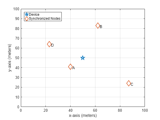
Calculate the actual distance and time of flight (TOF) between nodes and the device.
actualDistances = sqrt(sum((nodeLoc - deviceLoc).^2, 2));
c = physconst('LightSpeed'); % speed of light (m/s)
actualTOF = actualDistances/c;

SNR = 30;  % in dB
Configure Blinks
Use a short (IEEE 802.15.4 MAC) data frame as a blink.
numBlinks = 1;

% MAC layer:
payload = '00';
cfg = lrwpan.MACFrameConfig( ...
        FrameType='Data', ...
        SourceAddressing='Short address', ...
        SourcePANIdentifier='AB12', ...
        SourceAddress='CD77');
blinkMAC = lrwpan.MACFrameGenerator(cfg,payload);

% PHY layer:
% Ensure the Ranging field is enabled.
% Also set the proper PSDU length.
blinkPHYConfig = lrwpanHRPConfig( ...
    Mode='HPRF', ...
    STSPacketConfiguration=1, ...
    PSDULength=length(blinkMAC)/8, ...
    Ranging=true);
blinkPHY = lrwpanWaveformGenerator( ...
    blinkMAC, ...
    blinkPHYConfig);

% Cache preamble, to use in preamble detection.
% Get the 1st instance out of the Nsync=PreambleDuration repetitions.
indices = lrwpanHRPFieldIndices(blinkPHYConfig); % length (start/end) of each field
blinkPreamble = blinkPHY( ...
    1:indices.SYNC(end)/blinkPHYConfig.PreambleDuration); % 1 of the Nsync repetitions
Run Simulation
In the simulation loop, a blink propagates to each node with a propagation delay that is determined by their distinct distance. Next, each pair of nodes calculates the difference of their blink arrival times (TDOAs).
vfd = dsp.VariableFractionalDelay;
arrivalTime = zeros(1,numNodes);

for idx = 1:numBlinks
  for node = 1:numNodes
    % Transmission and reception of blink
    % Each node receives a specifically delayed version of the blink
    tof = actualTOF(node);
    samplesToDelay = tof * blinkPHYConfig.SampleRate;
    reset(vfd);
    release(vfd);
    vfd.MaximumDelay = ceil(1.1*samplesToDelay);
    delayedBlink = vfd( ...
        [blinkPHY; zeros(ceil(samplesToDelay), 1)], ...
        samplesToDelay);

    % Add white Gaussian noise
    receivedBlink = awgn(delayedBlink,SNR);

    % Node receiver detection of preamble
    preamPos = helperFindFirstHRPPreamble( ...
        receivedBlink,blinkPreamble,blinkPHYConfig);

    % Transmit each blink at t=0 of each period. The blink arrives
    % at different instances at each node, due to their dissimilar
    % distance to the device.
    arrivalTime(node) = ( ...
        preamPos - indices.SYNC(end) / ...
        blinkPHYConfig.PreambleDuration)/blinkPHYConfig.SampleRate;
  end
end

% TDOA estimates with the 1st node as the reference node
tdoaEst = arrivalTime(2:end) - arrivalTime(1);
Ideally, the position of the device is at the intersection of hyperbolic surfaces corresponding to the TDOAs of different node pairs. However, in the existence of noise, different hyperbolic surfaces may not intersect at the same point. In this example, we use a robust positioning algorithm implemented in tdoaposest (Phased Array System Toolbox) to localize the device.
% Default setup for unknown TDOA variance
tdoaVar = ones(1,numel(tdoaEst));

% TDOA position estimate
tgtPosEst = tdoaposest(tdoaEst,tdoaVar,nodeLoc');

% Root mean squared (RMS) error of the position estimate
RMSE = rmse(tgtPosEst,deviceLoc');
disp(['RMS Positioning error = ', num2str(RMSE), ' meters.'])
RMS Positioning error = 0.038284 meters.
% View true and estimated node positions
rngDiffEst = tdoaEst * c;
helperPlotTDOAPositions(rngDiffEst,tgtPosEst,nodeLoc');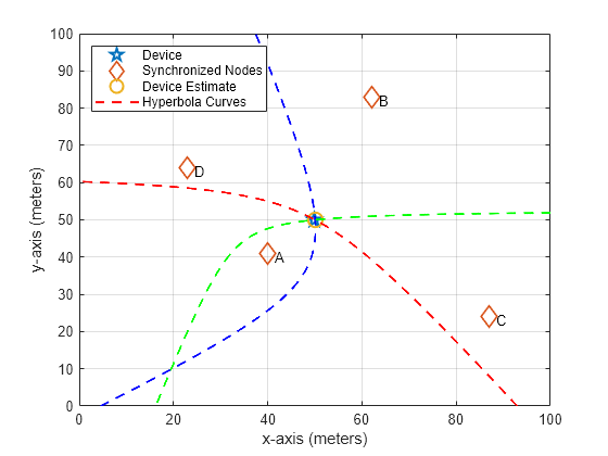
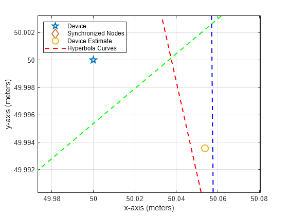
Zoom in to estimation area:
zoomInToEstimationArea(deviceLoc,tgtPosEst);
For localization methods that rely on estimating the time of arrival, errors in the distance estimate are primarily caused when the arrival time is not an integer multiple of the sample time. The largest distance error for such localization methods occurs when the arrival time lasts half a sample time more than an integer multiple of sample time. The smallest distance error occurs when the arrival time is an integer multiple of sample time. For the higher pulse repetition frequency (HRPF) mode of the high-rate pulse repetition frequency (HRP) PHY used in this example, the symbol rate is 499.2 MHz and the number of samples per symbol is 10. The maximum distance estimation error is , which is approximately 3 cm.
In general, the larger channel bandwidth in UWB corresponds to shorter symbol duration and smaller ranging error as compared to narrowband communication. For the narrowband communication as specified in IEEE 802.11az, the channel bandwidth ranges from 20 MHz to 160 MHz. Considering the maximum distance error for narrowband communication, estimates for the localization error lie between 0 and 10 cm for 160 MHz and between 0 and 75 cm for 20 MHz. For more information regarding positioning with IEEE 802.11az, see the 802.11az Positioning Using Super-Resolution Time of Arrival Estimation (WLAN Toolbox) example and the 802.11az Three-Dimensional Tracking Using Time of Arrival Estimation (Phased Array System Toolbox) example.
Further Exploration
This example uses the following objects and functions:
lrwpanHRPConfig: HRP waveform configurationlrwpanWaveformGenerator: Create an IEEE 802.15.4a/z HRP UWB waveformlrwpan.MACFrameConfig: Create configuration for 802.15.4 MAC frames
lrwpan.MACFrameGenerator: Generate 802.15.4 MAC frames
The API and functionality of undocumented utilities may change in the future. To view the source code of the undocumented utilities, use the edit function.
function zoomInToEstimationArea(deviceLoc,tgtPosEst)
% Zoom 2D plane into region around device location

  allX = [deviceLoc(1); tgtPosEst(1)];
  allY = [deviceLoc(2); tgtPosEst(2)];
  minX = min(allX);
  maxX = max(allX);
  minY = min(allY);
  maxY = max(allY);
  axis([ ...
      minX-0.5*(maxX-minX), ...
      maxX+0.5*(maxX-minX), ...
      minY-0.5*(maxY-minY), ...
      maxY+0.5*(maxY-minY)])
end
References
1 - "IEEE Standard for Low-Rate Wireless Networks," in IEEE Std 802.15.4-2020 (Revision of IEEE Std 802.15.4-2015), pp.1-800, 23 July 2020, doi: 10.1109/IEEESTD.2020.9144691.
2 - "IEEE Standard for Low-Rate Wireless Networks – Amendment 1: Enhanced Ultra Wideband (UWB) Physical Layers (PHYs) and Associated Ranging Techniques," in IEEE Std 802.15.4z-2020 (Amendment to IEEE Std 802.15.4-2020), pp.1-174, 25 Aug. 2020, doi: 10.1109/IEEESTD.2020.9179124.
3 - Wong, S.; Zargani, R. Jassemi; Brookes, D. & Kim, B. "Passive target localization using a geometric approach to the time-difference-of-arrival method", Defence Research and Development Canada Scientific Report, DRDC-RDDC-2017-R079, June 2017, pp. 1-77.