Recovery of IEEE 802.15.4z UWB Signals
This example shows how to implement a practical IEEE® 802.15.4z™ PHY receiver that recovers and decodes UWB waveforms captured over the air by using the Communications Toolbox™.
IEEE 802.15.4z [ 2 ] specifies an amendment to the high rate pulse repetition frequency (HRP) UWB PHY from IEEE 802.15.4 [ 1 ]. This amendment introduces a new, higher pulse repetition frequency (HPRF) operational mode that uses PRF as high as 249.6 MHz.
Setup
This example decodes a repeated version of an HPRF (higher pulse repetition frequency) UWB 802.15.4z signal that is transmitted over the air. You can create the transmitted UWB signal as follows:
rng(7, 'twister');
psduTx = randi([0, 1], 1016, 1);
cfgTx = lrwpanHRPConfig(Mode='HPRF', PSDULength=length(psduTx)/8, SamplesPerPulse=2);
waveTx = lrwpanWaveformGenerator(psduTx, cfgTx);
For the transmission, the example uses an NI™ PXI chassis together with two NI PXIe-5840 vector signal transceivers (VST). The vector signal generator (VSG) of one VST transmits the UWB waveform, and the vector signal analyzer (VSA) of the other VST receives the UWB waveform. Each VST uses an FXUWB10 Taoglas UWB antenna. The transmission occurs at channel 3, with a center frequency of 4.9928 GHz and a bandwidth of 499.2 MHz. The VSTs can operate at a 1 GHz sample rate, so the Nyquist sampling theorem is marginally satisfied (2 x 499.2 = 998.4 MHz).

The two VSTs use different clocks (one uses the onboard clock and the other uses the PXI clock). This configuration is representative of most wireless links, where the two end points do not have synchronized clocks.
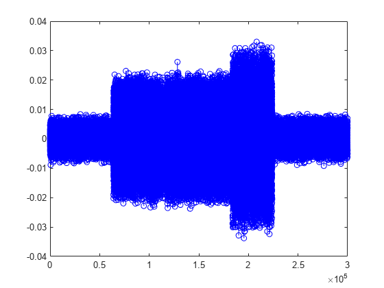
The following MAT file contains the received signal, which contains a single HPRF frame in its entirety.
load uwbCapture.mat
plot(real(capturedHPRF), 'b-o')
Overview
The IEEE 802.15.4z receiver in this example comprises two parts: a signal recovery compenent and a signal decoding component.
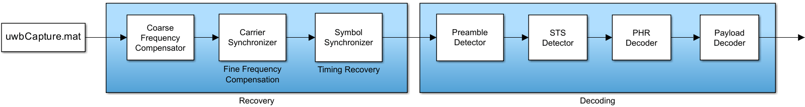
The signal recovery component performs frequency compensation (both coarse and fine), as well as timing recovery.
The signal decoding component detects the preamble start, identifies the STS packet configuration (presence and position of scrambled timestamp sequence), and decodes the PHY header (PHR) and the payload.
Finally, the decoded PSDU is compared with the known transmitted PSDU, to calculate BER over the UWB channel.
This 15.4z receiver is expected to work for signals that:
Follow the HPRF mode of 802.15.4z.
Use a 91-symbol preamble code (i.e., code index greater than 25).
Contain a payload whose length is unequal from the length of STS segments.
Frequency Compensation
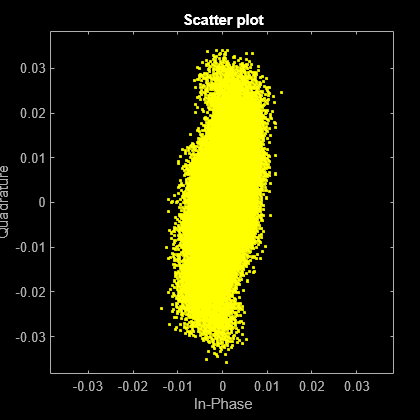
Because the transmitter and receiver are not synchronized, a frequency offset is present in the received frame. A scatter plot shows this effect, as the constellation rotates.
scatterplot(capturedHPRF)

Compensation for frequency offset is a two-step process: first, coarse frequency compensation is performed and then fine frequency compensation follows.
Coarse Frequency Compensation
To coarsely compensate for frequency offset, this example uses the comm.CoarseFrequencyCompensator System object™ for PAM modulation, as the HPRF signal uses ternary symbols (-1, 0, 1).
rxSPC = 2;      % Samples Per Chip/Pulse, given receive-side A/D
Fs = 499.2e6 * rxSPC;
coarseFC = comm.CoarseFrequencyCompensator(Modulation='PAM', SampleRate=Fs, FrequencyResolution=1e3);
[coarseFCsignal, freqEst] = coarseFC(capturedHPRF);
fprintf('Coarse frequency offset: %.2f MHz\n', freqEst/1e6)
Coarse frequency offset: 2.73 MHz
The effect of coarse frequency compensation is clearly visible in the constellation diagram, as the extent of signal rotations is reduced dramatically.
scatterplot(coarseFCsignal)
Fine Frequency Compensation
The second step is to use comm.CarrierSynchronizer (for PAM modulation) for fine frequency compensation.
fineFC = comm.CarrierSynchronizer(Modulation='PAM', SamplesPerSymbol=rxSPC);
[fineFCsignal, phaseEst] = fineFC(coarseFCsignal);
scatterplot(fineFCsignal)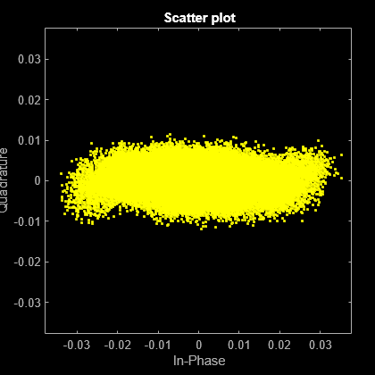
Indeed, the compensated signal converges to the x-axes, as the HPRF signal is real. Some complex noise is present.
Timing Recovery
Another consequence of the lack of synchronization between the transmitter and the receiver is sample rate offset, which causes symbols to be sampled suboptimally and at instances that vary relatively to the symbol duration.
Timing recovery compensates for this effect. The "early-late" synchronization algorithm is selected, as it does apply for ternary symbols (-1, 0, 1) that are pulse-shaped with an Buttterworth filter (IIR).
fineFCsignalReal = real(fineFCsignal);
symbolSync = comm.SymbolSynchronizer(Modulation='PAM/PSK/QAM', SamplesPerSymbol=rxSPC, TimingErrorDetector='Early-Late (non-data-aided)');
recoveredHPRF = symbolSync(fineFCsignalReal);
Due to the substantial amount of noise, the constellation is essentially continuous along the x-axis instead of forming three distinct clouds around the ternary symbols.
scatterplot(recoveredHPRF)

At this stage, signal recovery is complete and the rest of this example focuses on decoding the recovered waveform.
Preamble Detection
The received UWB waveform begins at an unknown instance. A practical receiver performs preamble detection to find the beginning of the PHY frame. Toward this end, the example uses comm.PreambleDetector to locate the synchronization (SYNC) field.
However, the SYNC field may be composed from one out of many possible code sequences. The receiver does not use any transmit-side information and considers all possible codes until it detects the SYNC field.
Moreover, frequency compensation may introduce phase ambiguity. That is, the polarity of the ternary UWB signal may be inverted. As a result, preamble detection also resolves phase ambiguity by considering all possible phase combinations.
Tpream = 5; % manual, iterative specification; threshold can increase until only 1 code detected
Tnoise = 0.01; % used for energy detection, toward specification of the Preamble Detector threshold
Tzero = 25/100; % amplitude threshold for zero symbols, as percentage of highest amplitude - should be higher than noise

cfgRcv = lrwpanHRPConfig(Mode='HPRF', SamplesPerPulse=rxSPC); % create an object to keep track of the received-frame properties
preambleCodesHPRF = 25:32;
preambleDet = comm.PreambleDetector;
syncFound = false;
codeIdx = preambleCodesHPRF(1)-1;
hprfPreambleDurations = [16, 24, 32, 48, 64, 96, 128, 256];
while ~syncFound && codeIdx < max(preambleCodesHPRF) % consider all codes until detection
  codeIdx = codeIdx+1;
  for polarity = [-1 1]                               % consider all polarities until detection
    % create SYNC from spread code:
    code = polarity * lrwpan.internal.HRPCodes(codeIdx);
    spreadingFactorHPRF = cfgRcv.PreambleSpreadingFactor; % spreading factor, L (always 4 for HPRF mode)
    preamble = zeros(length(code) * spreadingFactorHPRF, 1);
    preamble(1:spreadingFactorHPRF:end) = code;

    release(preambleDet);
    preambleDet.Preamble = preamble;
    meanCorr = mean(abs(filter( flipud(preamble), 1, recoveredHPRF(recoveredHPRF>Tnoise))));
    preambleDet.Threshold = Tpream*meanCorr;
    [preamPos, corrMat] = preambleDet(recoveredHPRF);
    durationIdx = find(numel(preamPos) > hprfPreambleDurations, 1, 'last');
    if ~isempty(durationIdx)
      cfgRcv.PreambleDuration = hprfPreambleDurations(durationIdx);
      syncFound = true;
      break; % preamble found, no need to explore other polarity
    end
  end
end
if syncFound
  fprintf('Found SYNC for code #%d.', codeIdx);
  cfgRcv.CodeIndex = codeIdx; % keep track of identified frame characteristics
else
  error('No SYNC field found in the input data.');
end
Found SYNC for code #25.
% Slice remaining capture with integrate and dump (frame length is unknown for now, it is in the PHR)
recoveredHPRF = recoveredHPRF/max(abs(recoveredHPRF)); % normalize amplitude
frameStart = preamPos(1)-length(preamble)+1;
ternarySymbols = polarity*recoveredHPRF(frameStart:end);
ternarySymbols(abs(ternarySymbols)<Tzero) = 0;
ternarySymbols(ternarySymbols>Tzero) = 1;
ternarySymbols(ternarySymbols<-Tzero) = -1;
Start-of-Frame Delimiter
The start-of-frame delimiter (SFD) follows the synchronization (SYNC) field. For the HPRF mode, the length of the SFD field may be 4, 8, 16, or 32 symbols. The receiver does not use any transmit-side information and searches for all possible SFDs.
% Detect SFD by identifying 95% match on a chip-by-chip basis
berThr = 1 - 95/100;

sfdFound = false;
sfdStart = 1+length(preamble)*cfgRcv.PreambleDuration;
for sfdNum = 0:4 % SFD values from Table 15-7c
  cfgRcv.SFDNumber = sfdNum;
  sfd = lrwpan.internal.getSFD(cfgRcv);
  spreadedSFD = sfd.*preamble * polarity;
  spreadedSFD = spreadedSFD(:);

  bitErrs = sum(spreadedSFD ~= ternarySymbols(sfdStart:sfdStart+length(spreadedSFD)-1));
  sfdBER = bitErrs/length(spreadedSFD);
  if sfdBER < berThr
    sfdFound = true;
    break;
  end
end
if sfdFound
  fprintf('Found SFD #%d.', sfdNum);
else
  warning('No SFD was found after SYNC.')
end
Found SFD #0.
STS
The scrambled timestamp sequence (STS) packet configuration is also unknown at the receiver. That is, it is not known whether STS and payload exist and in what order. Similarly, it is unknown how many STS segments exist and what their length is.
The receiver infers the answer to these questions by identifying STS gaps.
numChipsPerGap = 512; % Section 15.2.9 in [2].
sfdEnd = sfdStart + length(spreadedSFD) - 1;
gapStarts = [];
idx = sfdEnd+1;
while idx <= length(ternarySymbols)-numChipsPerGap+1
  if ~any(ternarySymbols(idx:idx+numChipsPerGap-1))  % 512 chips long gap found
    if ~isempty(gapStarts) && idx == gapStarts(end)+512 % end of frame found, do not treat as STS gap
      gapStarts(end) = [];
      ternarySymbols = ternarySymbols(1:idx);
      break;
    end
    gapStarts = [gapStarts idx]; %#ok<AGROW>
    idx = idx + numChipsPerGap; % go to the end of the gap
    continue;
  end

  % go to the last non-zero, to avoid pointless comparisons
  nextIncr = find(ternarySymbols(idx+1 : idx+numChipsPerGap), 1, 'last');
  if isempty(nextIncr)
    nextIncr = numChipsPerGap;
  end
  idx = idx + nextIncr+1;
end
stsAfterSFD = ~isempty(gapStarts) && gapStarts(1) == sfdEnd+1;
if isempty(gapStarts)
  cfgRcv.STSPacketConfiguration = 0;
else
  cfgRcv.NumSTSSegments = max(1, numel(gapStarts)-1); % 1 segment if frame finishes with gap
  cfgRcv.STSPacketConfiguration = 0 + (cfgRcv.NumSTSSegments>0) + ~stsAfterSFD; % STSPacketConfiguration = 3 not supported
end

% Last gap does not start at end of symbol because the last L-1 symbols are zeros
if stsAfterSFD
  cfgRcv.STSSegmentLength = (diff(gapStarts(1:2))-numChipsPerGap + spreadingFactorHPRF-1)/numChipsPerGap; % in units of 512 chips
elseif ~isempty(gapStarts)
  cfgRcv.STSSegmentLength = (length(ternarySymbols)-gapStarts -numChipsPerGap + spreadingFactorHPRF-1)/numChipsPerGap; % in units of 512 chips
end

if cfgRcv.STSPacketConfiguration
  fprintf('Found %d STS segment(s) of length %d; STS packet configuration is %d.\n', cfgRcv.NumSTSSegments, cfgRcv.STSSegmentLength, cfgRcv.STSPacketConfiguration)
  stsLen = numChipsPerGap*(cfgRcv.NumSTSSegments+1) + cfgRcv.NumSTSSegments * cfgRcv.STSSegmentLength * 512;
else
  fprintf('Found no STS.\n');
  stsLen = 0;
end
Found 1 STS segment(s) of length 64; STS packet configuration is 1.
PHR
The PHY header (PHR) contains information such as the length of the PHY service data unit (PSDU). For the HPRF mode, both the header and the payload may follow one of two modulation variants, depending on the mean pulse repetition frequency (PRF), which can be either 124.8 or 249.6 MHz. Each modulation variant uses symbols of different lengths and with different guardband format (see Figure 15-11b-e in [ 2 ]).
Moreover, the symbol length in the PHR is also determined by the constraint length of the convolutional coding, which is either 3 or 7 (see Tables 15-10c-f in [ 2 ]).
if ~stsAfterSFD
  phrStart = sfdEnd+1;
else
  phrStart = sfdEnd + 1 + stsLen;
end

% Need to find modulation type (124.8 vs 249.6 MHz)
% Guarbands are the distinguishing factor (75% vs 50% of symbols, respectively)
numPHRBits = 19;
minSymbolDuration = 16; % in chips, out of all the data-rate, coding combinations
% The PHR will span at least 19x16 chips. Check within that range for
% guarband statistics:
numZeros = sum(0 == ternarySymbols(phrStart: phrStart+numPHRBits*minSymbolDuration-1));
zerosPct = numZeros/(numPHRBits*minSymbolDuration);
mode249MHz = zerosPct< (50 + (75-50)/2)/100;
if mode249MHz
  cfgRcv.MeanPRF = 249.6;
else
  cfgRcv.MeanPRF = 124.8;
end

% Next, determine if convolutional coding uses constraint
% length 3 or 7, as different symbol mapping is used (Tables 15-10c-f in [2]).
for CL = [3 7]
  cfgRcv.ConstraintLength = CL;
  isPHR = true;
  [cwPHR, phrEnd] = helperUWBHPRFDemod(isPHR, ternarySymbols, phrStart, cfgRcv);
  [secdedPass, PSDULength] = helperUWBPHRDecode(cwPHR, cfgRcv, CL);
  if secdedPass
    cfgRcv.PSDULength = PSDULength;
    break;
  end
end
Payload
The PHR decoding identifies the mean PRF and the constraint length. Therefore, the payload can be decoded and compared with the known transmitted PSDU.
payloadStart = phrEnd+1;
decodedPSDU = helperUWBPayloadDecode(ternarySymbols, payloadStart, cwPHR, cfgRcv);

[~, ber] = biterr(psduTx, decodedPSDU);
fprintf('Bit error rate: %0.2f\n', ber)
Bit error rate: 0.00
The bit error rate is zero, even though the chip error rate was higher (1%) during the SFD identification. These chip errors are corrected by the spreading and repetition performed by the HPRF modulation scheme, as well as by the convolutional and Reed-Solomon encoding of the HRP PHY.
References
1. "IEEE Standard for Low-Rate Wireless Networks," in IEEE Std 802.15.4-2020 (Revision of IEEE Std 802.15.4-2015), pp.1–800, 23 July 2020, DOI: 10.1109/IEEESTD.2020.9144691.
2. "IEEE Standard for Low-Rate Wireless Networks—Amendment 1: Enhanced Ultra Wideband (UWB) Physical Layers (PHYs) and Associated Ranging Techniques," in IEEE Std 802.15.4z-2020 (Amendment to IEEE Std 802.15.4-2020), pp.1–174, 25 August 2020, DOI: 10.1109/IEEESTD.2020.9179124.