Manual Host-Radio Hardware Setup
To implement the features in the Communications Toolbox™ Support Package for USRP™ Embedded Series Radio, you must configure the host computer and the radio hardware for proper communication. After the support package is installed, follow these steps to manually set up the hardware.
Step 1. Complete Hardware Checklist
Use this list to confirm that you have all required hardware and accessories to complete the hardware setup.
1. Gigabit Ethernet connection
This connection is often referred to as a network connection. You can use either an integrated network interface card (NIC) with a Gigabit Ethernet cable or a USB 3.0 Gigabit Ethernet adapter dongle. This connection is necessary for transmitting data, such as a programming file, from the host computer to the radio hardware. It is also necessary for sending and receiving signals to and from the radio hardware.
Note
Ethernet connection is the only supported method for connecting the radio hardware and host computer.
To have simultaneous Internet access in the absence of a wireless connection, the host computer must have two Ethernet connections.
2. SD card reader and writable SD card
If the host machine does not have an integrated SD card reader, use an external USB SD card reader. For USRP E310 and USRP E312 radio hardware, you need a microSD card.
3. Supported radio hardware
For a list of supported radio hardware, see Hardware Support. Do not connect or turn on the device until you are prompted at a later step.
4. Ethernet cable
You need this cable to connect the radio hardware to the host.
5. Antennas or a loopback cable
You need antennas for transmitting and receiving signals over the air.
Step 2. Set Up Support Package in MATLAB
To work with the support package in MATLAB®, you must create a radio object for your radio hardware. In the following
example, dev is a radio object interfacing an E3xx embedded series radio
hardware.
dev = sdrdev('E3xx');sdrdev also sets up architecture-specific environment variables for
the radio hardware. These variables enable communication between MATLAB or Simulink® and the radio hardware.
For more information on creating radio objects, see sdrdev.
Step 3. Configure Host Computer
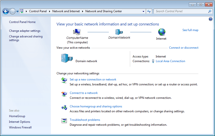
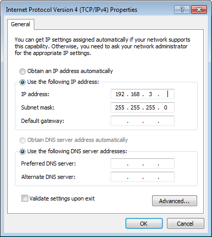
To connect the radio hardware to the host, you must configure an available network connection for it on the host. Follow the steps outlined for your specific operating system.
Step 4. Write Firmware
You need an SD memory card that is configured with the firmware of this support package. The firmware includes the embedded software and the FPGA programming file necessary for using the radio hardware as an I/O peripheral. If you have already configured an SD card with this image, skip this step.
Insert a 4 GB or larger SD memory card into the memory card reader on the host computer. Ensure that the SD card has only one partition with a FAT16 or FAT32 file system.
Note
If you use a lockable SD card adapter for the microSD card, you must unlock it first.
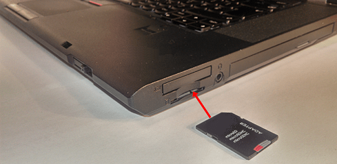
At the MATLAB command prompt, enter the following command:
downloadImage(dev,'BoardName','E3xx', ...
   'SDCardLocation',SDCardDrive)
dev— Radio object created using thesdrdevfunction in Step 2. Set Up Support Package in MATLAB.SDCardDrive— Name of the SD card drive on the host computer, specified as a character vector. For example,'/media/F8FF-1F5F'or'S:'
For example:
dev = sdrdev('E3xx');
downloadImage(dev,'BoardName','E3xx', ...
    'SDCardLocation','S:')
Step 5. Connect Radio Hardware
Connect USRP E310 or USRP E312 Radio Hardware
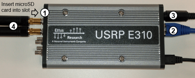
Remove the microSD memory card from the host computer and insert it into the radio hardware.
Connect an Ethernet cable to the radio hardware. Connect the other end of the Ethernet cable to the network connection selected previously.
Connect the power cable to the radio hardware.
Connect the antennas or loopback cable.
Turn the board power on.
Wait until you see the TRX-B LED flashing, that indicates that the radio hardware is ready.
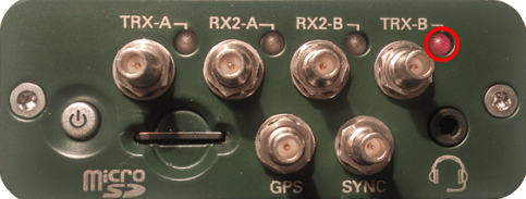
If the LED does not light up after one minute, verify that the SD card has been properly configured.
When the LEDs light up as indicated, proceed to the next step.
Step 6. Verify Radio Hardware Setup
Before you can verify the setup, you must start the radio hardware properly. Wait until the radio hardware is ready as indicated in the previous step.
Check host-radio communication by calling the testConnection
function. When calling testConnection, use the radio object that you
created in Step 2. Set Up Support Package in MATLAB
and the host IP address that you configured in Step 3. Configure Host Computer.
testConnection(dev,'192.168.3.1');
Successful Connection
If the function displays All tests PASSED, then the host is
communicating successfully with the radio hardware.
Continue with one of the following options.
To work with the hardware-software co-design workflow, you must install and configure third-party tools and additional support packages. See Installation for Hardware-Software Co-Design.
To explore radio I/O capabilities, see What to Do After Installation.
Unsuccessful Connection
If the function returns a timeout or other error, then the host is not communicating with the radio hardware.
For example:
Warning: There was no response from the hardware. Read the
documentation on how to diagnose connectivity issues.
 - Ensure the host and hardware are physically connected via GigE.
 - Ensure the host NIC is configured properly.
 - Check that the IPAddress of the hardware is specified correctly.
Return to Step 5. Connect Radio Hardware. Before calling the
info function, make sure that the radio hardware is properly
connected to the host. If you still have trouble, check Common Problems and Fixes.

