RDS/RBDS and RadioText Plus (RT+) FM Receiver
This example shows how to extract program or song information from FM radio stations using the RDS or RBDS standard and, optionally, the RadioText Plus (RT+) standard. You can use a previously captured signal, or receive signals over-the-air in real time using an RTL-SDR radio, an ADALM-PLUTO radio, or a USRP™ radio.
Required Hardware and Software
By default, this example runs using recorded data from a file. Optionally, you can receive signals over-the-air using a device that supports the required sample rate of 228 ksps. For this, you also need one of the following:
RTL-SDR radio and Communications Toolbox Support Package for RTL-SDR Radio.
ADALM-PLUTO radio and Communications Toolbox Support Package for ADALM-PLUTO Radio.
USRP B2xx series radio and Communications Toolbox Support Package for USRP Radio. For information on supported radios, see Supported Hardware and Required Software.
USRP E3xx series radio and Wireless Testbench Support Package for NI USRP Radios. For information on supported radios, see Supported Radio Devices (Wireless Testbench).
Background
RBDS and RDS are very similar standards specifying how to supplement FM radio signals with additional information. RBDS is used in North America, while RDS was originally used in Europe and evolved to an international standard. RBDS and RDS comprise 3 layers:
Physical Layer (Layer 1)
Data-link Layer (Layer 2)
Session and presentation Layer (Layer 3)
Physical Layer (Layer 1)
The RBDSPhyDecoder helper receives the captured signal from a file or the live signal from the radio and performs these steps:
FM demodulation: Once the FM signal is demodulated, the RDS/RBDS signal resides at the 57 kHz +/- 2.4 kHz band. Be aware that the RDS/RBDS signal is transmitted with relatively low power, so it is not always visible in the FM spectrum as shown in this figure.
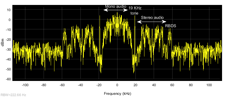
FM signals contain a pilot tone at 19 kHz, which can be used as a phase and frequency reference for coherent demodulation of the RDS/RBDS signal at 57 kHz and the stereo audio at 38 kHz. Pilot tones at 38 kHz and 57 kHz can be generated by doubling and tripling the frequency of the 19 kHz pilot tone [ 2 ].
Processing steps for coherent demodulation of the RDS/RBDS signal are:
Bandpass filtering: The PHY receiver conducts bandpass filtering at 19 kHz and 57 kHz, to isolate the pilot tone and the RDS/RBDS signal, respectively.
Frequency tripling: Raise the complex representation of the 19 kHz pilot tone to the 3rd power to triple its frequency and obtain a 57 kHz pilot tone.
AM Demodulation: RDS and RBDS symbols are generated at an 1187.5 Hz rate and are AM-modulated to a 57 kHz carrier. The 57 kHz RDS/RBDS signal can be coherently demodulated with a 57 kHz carrier that is locked in frequency and phase. Typically, the frequency-tripled 19 kHz pilot tone suffices for coherent demodulation. The next figures show the 19 kHz and 57 kHz pilot tones, the 57 kHz RDS/RBDS signal, and the AM-demodulated baseband RDS/RBDS signal.
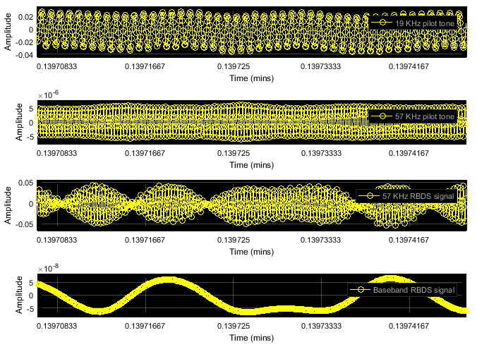
At the same time, there exist several FM stations whose 57 kHz RDS/RBDS signal exhibits a time-varying phase offset from the 19 kHz pilot tone and its frequency-tripled version. The PHY receiver contains a Costas loop to compensate for such time-varying phase offsets.
Costas loop: The Costas loop performs 2 orthogonal AM demodulations, one demodulation with a 57 kHz sine and another with a 57 kHz cosine. The sampling rate of the received signal is carefully chosen as 228 kHz, which provides 4 samples per 57 kHz cycle. Therefore, a one sample delay of the 57 kHz pilot tone results to a one quarter wavelength phase offset, and allows us to generate a cosine wave from a sine wave. The sine-demodulated signal corresponds to the coherent demodulation output. The cosine-demodulated signal is used for detection of phase error. The products of the 57 kHz RDS/RBDS signal with the sine/cosine waves are low-pass filtered with the filter specified in Sec. 1.7 of [ 1 ]. The product of the two filter outputs is an error signal. The larger it is, the more the 19 kHz pilot tone is delayed to behave more like the cosine-based demodulator.
Clock extraction: To perform biphase symbol decoding, a clock matching the RDS/RBDS symbol rate of 1187.5 Hz is extracted from the 19 kHz pilot tone. Note, 1187.5 Hz x 16 = 19 kHz. To account for frequency offsets, frequency division is used to extract the clock from the 19 kHz pilot tone. Since the frequency division operation provides multiple correct answers, the baseband RDS/RBDS signal serves as training data that aid in the determination of the desired output.
Biphase symbol decoder: RDS and RBDS use bi-phase-level (bi- -L) coding, which is commonly known as Manchester coding. In each clock cycle, the RDS/RBDS symbol takes two opposite amplitude values, either a positive followed by a negative, or a negative followed by a positive. The biphase symbol decoder negates the second amplitude level, so that each symbol holds the same amplitude level throughout the entire clock cycle. The new clock-wide amplitude level corresponds to the symbol's bit representation. These plots correspond to the waveforms #1-6 in Figure 2 of [ 1 ].
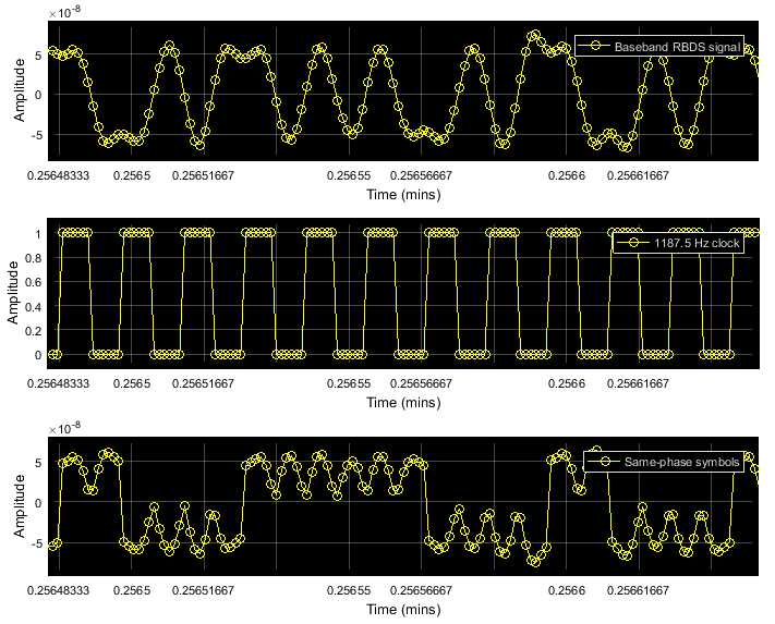
To obtain each symbol's bit value, the waveform is integrated over each clock cycle, and the outcome is compared to zero (slicer).
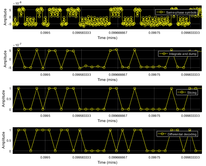
Differential decoding: Finally, the bits are differentially decoded to revert the differential encoding at the transmitter.
Data-link Layer (Layer 2)
Layer 2 is implemented using the RBDSDataLinkDecoder helper. This layer is responsible for synchronization and error correction.
The bit output of the PHY layer is logically organized in 104-bit groups comprising four 26-bit blocks. Each block contains a 16-bit information word and 10 parity bits (see Figure 8 in [ 1 ]). A distinct 10-bit offset word is modulo-2 added to the parity bits of each block.
Synchronization: Initially, block and group boundaries are sought exhaustively using a sliding window of 104 bits. For each 104-bit window, the 4 offset words are sought at the last 10 bits of each 26-bit block. An offset word is identified if no bit errors are detected by the
RBDSErrorDetectionhelper. Once the offset words are identified, group-level synchronization is attained and the exhaustive sliding-window processing stops. Subsequently, the next 104 bits will be treated as the next group.
If future groups contain bit errors and the offset words cannot be identified at their expected position, synchronization may be lost. In this case, Layer 2 first examines the possibility of 1-bit synchronization slips, exploiting the fact that the first information word (16 bits) is always the same for all bit groups. If the first information word is found dislocated by 1 bit (either leftward or rightward), synchronization is retained and the group boundaries are adjusted accordingly. If bit errors persist for 25 group receptions and at the same time synchronization cannot be reestablished using such leftward/rightward 1-bit shifts, then synchronization is lost and Layer 2 re-enters the exhaustive, sliding-window-based search for synchronization.
Error correction: The RDS/RBDS error correction code is a (26, 16) cyclic code shortened from (341, 331). The
RBDSErrorCorrectionhelper uses the shift-register scheme described in Annex B of [ 1 ].
Session and Presentation Layer (Layer 3)
Layer 2 removes the parity/offset bits, therefore Layer 3 receives groups of 64-bits, comprising four 16-bit blocks. There exist up to 32 different group types, each labeled with a number from 0 to 15 and the letter 'A' or 'B', for example, 0B, 2A, 3A. The format of each group can be fixed or it can be abstract if this group is allocated for an Open Data Application (ODA, see list in [ 3 ]).
Layer 3 is implemented using the RBDSSessionDecoder helper. This object supports decoding of the 0A, 0B, 2A, 2B, 3A, 4A, 10A fixed-format group types.
0A and 0B convey an 8-character string, which typically changes in a scrolling-text fashion.
2A and 2B convey longer 64- or 32-character strings.
3A registers ODAs and specifies their dedicated abstract-format group type.
4A conveys the system time.
10A further categorizes the program type, such as 'Football' for 'Sports' program type.
For ODAs, the RDS/RBDS receiver supports decoding of RadioText Plus (RT+). This ODA can break down the long 32- or 64-character string from group types 2A or 2B into two specific content types (for example, artist and song).
Registering ODA Implementations: RadioText Plus (RT+)
The RDS/RBDS receiver is extensible. ODA implementations can be specified using the registerODA' function of the RBDSSessionDecoder helper. This function accepts the hexadecimal ID of the ODA (ODA IDs can be found in [ 3 ]), and handles to the functions that process the main ODA group type, as well as the ODA-specific part of the 3A group type. For example, the session decoder RBDSSessionDecoder object can be extended for RadioText Plus (RT+) using this code:
rtID = '4BD7'; % hexadecimal ID of RadioText Plus (RT+)
registerODA(sessionDecoder, rtID, @RadioTextPlusMainGroup,
@RadioTextPlus3A);
Run the Example Code
Use the helperRBDSInit helper function to set RDS/RBDS system parameters. The commented code lines shows alternate settings to run the example from captured data or various SDRs. Use the helperRBDSConfig helper function to configure the RDS/RBDS system.
userInput = helperRBDSInit();
userInput.Duration = 10.8;
% userInput.SignalSource = 'File';
% userInput.SignalFilename = 'rbds_capture.bb';
% userInput.SignalSource = 'RTL-SDR';
% userInput.CenterFrequency = 98.5e6;
% userInput.SignalSource = 'ADALM-PLUTO';
% userInput.CenterFrequency = 98.5e6;
% userInput.SignalSource = 'USRP';
% userInput.CenterFrequency = 98.5e6;

[rbdsParam, sigSrc] = helperRBDSConfig(userInput);
Create and configure an FM broadcast receiver System object™ with the RDS/RBDS parameters.
fmBroadcastDemod = comm.FMBroadcastDemodulator(...
    'SampleRate',228e3, ...
    'FrequencyDeviation',rbdsParam.FrequencyDeviation, ...
    'FilterTimeConstant',rbdsParam.FilterTimeConstant, ...
    'AudioSampleRate',rbdsParam.AudioSampleRate, ...
    'Stereo',true);

% Create audio player
player = audioDeviceWriter('SampleRate',rbdsParam.AudioSampleRate);

% Layer 2 object
datalinkDecoder = RBDSDataLinkDecoder();

% Layer 3 object
sessionDecoder  = RBDSSessionDecoder();
% register processing implementation for RadioText Plus (RT+) ODA:
rtID = '4BD7';
registerODA( ...
    sessionDecoder,rtID,@RadioTextPlusMainGroup,@RadioTextPlus3A);

% Create the data viewer object
viewer = helperRBDSViewer();

% Start the viewer and initialize radio time
start(viewer)
radioTime = 0;
% Main loop
while radioTime < rbdsParam.Duration
    % Receive baseband samples (Signal Source)
    rcv = sigSrc();

    % Demodulate FM broadcast signals and play the decoded audio
    audioSig = fmBroadcastDemod(rcv);
    player(audioSig);

    % Process physical layer (Layer 1)
    bitsPHY = RBDSPhyDecoder(rcv, rbdsParam);

    % Process data-link layer (Layer 2)
    [enabled,iw1,iw2,iw3,iw4] = datalinkDecoder(bitsPHY);

    % Process session and presentation layer (Layer 3)
    outStruct = sessionDecoder(enabled,iw1,iw2,iw3,iw4);

    % View results packet contents (Data Viewer)
    update(viewer, outStruct);

    % Update radio time
    radioTime = radioTime + rbdsParam.FrameDuration;
end

% Stop the viewer and release the signal source and audio writer
stop(viewer);
release(sigSrc);
release(player);
Viewing Results
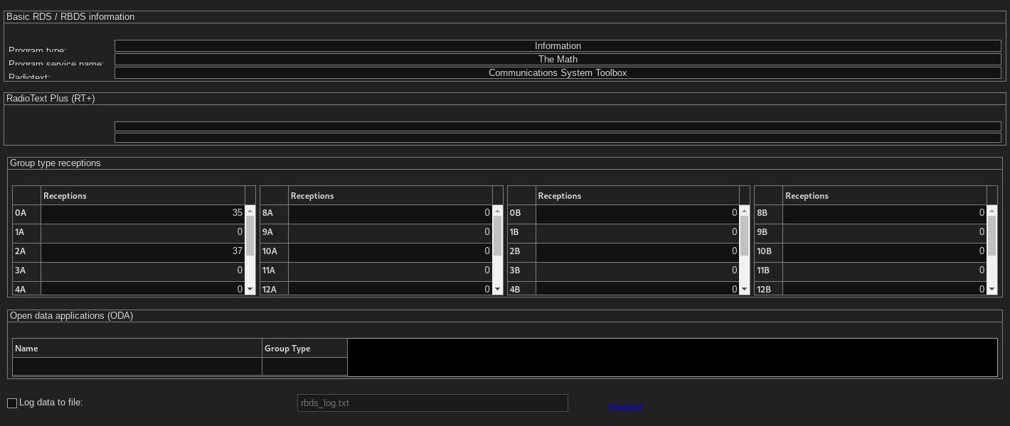
This window shows the processed RDS/RBDS data.
Basic RDS/RBDS information:
The first field contains the program type, which is conveyed by the second information word of all group types. If 10A group types are received, the first field also provides further characterization, such as, Sports \ Football.
The second field contains the 8-character text conveyed by 0A/0B groups. The displayed text wraps if the transmitted character string exceeds eight characters.
The third field contains the longer 32/64-character text conveyed by 2A/2B group types.
RadioText Plus (RT+): This section is populated if any 3A groups indicate that the RadioText Plus (RT+) ODA uses an abstract-format group type, such as 11A. Upon reception of this abstract group type, the 32/64-character text conveyed by groups 2A/2B will be split to two substrings. The two labels will be updated to characterize the substrings (such as Artist and Song).
Group type receptions: The tables provide a histogram displaying which group types have been received from a station and with what frequency. As a result, users may want to look at the logged data for further information that is not depicted in the graphical viewer (specifically, system time in 4A, alternate frequencies in 0A etc.).
Open data applications (ODA): If any 3A group types are received, this ODA list displays the name and the dedicated group type for each ODA received.
Further Exploration
You can further explore RDS/RBDS signals using the RBDSExampleApp app. The RBDSExampleApp app allows you to:
Select the source of the signal (capture file or RTL-SDR, ADALM-PLUTO or USRP).
Specify the station frequency (for RTL-SDR, ADALM-PLUTO or USRP).
Run Layers 1 and 2 of the RDS/RBDS receiver though generated C code. These are the most time-consuming parts of the RDS/RBDS chain and generating code can help you achieve real-time processing.
Disable audio playback.
Open scopes, such as a Spectrum Analyzer and Time Scopes, that analyze the received signal and illustrate the decoding process. Enabling scopes requires extra computational effort and may preclude real-time decoding. In this case, RDS/RBDS decoding may only be successful for captured signals loaded from a file.
Log RBDS fields from other group types by selecting Log data to file.
You can explore the RBDS implementation, initialization, and configuration in these functions and System objects:
RBDSPhyDecoderRBDSCostasLoopRBDSDataLinkDecoderRBDSSessionDecoderhelperRBDSInithelperRBDSConfig
References
1. National Radio Systems Committee, United States RBDS standard, April 1998
2. Der, Lawrence. "Frequency Modulation (FM) Tutorial". Silicon Laboratories Inc.
3. National Radio Systems Committee, List of ODA Applications in RDS
4. RadioText Plus (RT+) Specification
5. Joseph P. Hoffbeck, "Teaching Communication Systems with Simulink® and the USRP", ASEE Annual Conference, San Antonio, TX, June 2012