Simulation 3D Probabilistic Radar Configuration
Configure probabilistic radar signatures in 3D simulation environment
Libraries:
Automated Driving Toolbox /
Simulation 3D
Description
Note
Simulating models with the Simulation 3D Probabilistic Radar Configuration block requires Simulink® 3D Animation™.
The Simulation 3D Probabilistic Radar Configuration block configures the probabilistic radar signatures for actors in a 3D simulation environment. This environment is rendered using the Unreal Engine® from Epic Games®. To model the probabilistic radars, use Simulation 3D Probabilistic Radar blocks. The configured radar signatures apply to all Simulation 3D Probabilistic Radar blocks in your model.
Examples
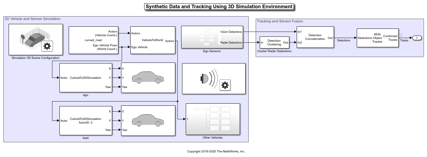
Simulate Vision and Radar Sensors in Unreal Engine Environment
Implement a synthetic data simulation for tracking and sensor fusion using Simulink and the Unreal Engine simulation environment.
Parameters
Radar targets — Identifiers corresponding to radar targets
[]
(default) | positive integer | L-length vector of unique positive integers
Identifiers that correspond to radar targets, specified as a positive integer or L-length vector of unique positive integers. L equals the number of radar targets for which you want to specify a nondefault radar cross section (RCS).
This table provides the identifiers and corresponding object types that radars can
detect in the default scenes that you can select from the Simulation 3D Scene
Configuration block. For example, to specify a nondefault RCS for a building
and a road, set Radar targets to [1,7]
. If you
are using a custom scene, in the Unreal® Editor, you can assign new object types to unused IDs. For more details,
see Apply Labels to Unreal Scene Elements for Semantic Segmentation and Object Detection. If a scene contains
an object that does not have an assigned ID, that object is assigned an ID of
0
. The detection of lane markings is not supported.
ID | Type |
---|---|
0 | None/default |
1 | Building |
2 | Not used |
3 | Other |
4 | Pedestrians |
5 | Pole |
6 | Lane Markings |
7 | Road |
8 | Sidewalk |
9 | Vegetation |
10 | Vehicle |
11 | Not used |
12 | Generic traffic sign |
13 | Stop sign |
14 | Yield sign |
15 | Speed limit sign |
16 | Weight limit sign |
17-18 | Not used |
19 | Left and right arrow warning sign |
20 | Left chevron warning sign |
21 | Right chevron warning sign |
22 | Not used |
23 | Right one-way sign |
24 | Not used |
25 | School bus only sign |
26-38 | Not used |
39 | Crosswalk sign |
40 | Not used |
41 | Traffic signal |
42 | Curve right warning sign |
43 | Curve left warning sign |
44 | Up right arrow warning sign |
45-47 | Not used |
48 | Railroad crossing sign |
49 | Street sign |
50 | Roundabout warning sign |
51 | Fire hydrant |
52 | Exit sign |
53 | Bike lane sign |
54-56 | Not used |
57 | Sky |
58 | Curb |
59 | Flyover ramp |
60 | Road guard rail |
61 | Bicyclist |
62-66 | Not used |
67 | Deer |
68-70 | Not used |
71 | Barricade |
72 | Motorcycle |
73-255 | Not used |
Radar cross sections (dBsm) — Radar cross sections
{}
(default) | real-valued Q-by-P matrix | L-length cell array of real-valued
Q1-by-P1,
…,
QL-by-PL
matrices
Radar cross sections of target actors, in decibels per square meter, specified as a matrix or cell array of matrices. Each matrix defines the RCS for the corresponding target actor specified by Radar targets.
If Radar targets is a scalar (that is, a single target actor), then specify Radar cross sections (dBsm) as a real-valued Q-by-P matrix, where:
Q is the number of elevation angle samples for the actor.
P is the number of azimuth angle samples for the actor.
If Radar targets is a vector (that is, multiple target actors), then specify Radar cross sections (dBsm) as a L-length cell array of real-valued Q1-by-P1, …, QL-by-PL matrices, where:
L is the number of actors.
Q1, …, QL are the number of elevation angle samples per actor.
P1, …, PL are the number of azimuth angle samples per actor.
Q and P can vary for each actor. For each RCS matrix:
The rows correspond to uniformly sampled elevation angles over the interval [0, 180].
The columns correspond to uniformly sampled azimuth angles over the interval [0, 360].
For example, the number of elevation and azimuth samples for RCS matrix
RCS
are as follows:
el = linspace(0,180,size(RCS,1)); az = linspace(0,360,size(RCS,2));
Default radar cross section (dBsm) — Default radar cross section
-20
(default) | real scalar
Default radar cross section, in decibels per square meter, specified as a real scalar. The block uses this RCS value for actors whose RCS is not specified by Radar cross sections (dBsm). If the model does not contain a Simulation 3D Scene Configuration block, then the default RCS assigned to actors in an Unreal Engine scenario is –20 dBsm.
Example: -10
Version History
Introduced in R2019bR2024a: Requires Simulink 3D Animation
Simulating models with the Simulation 3D Probabilistic Radar Configuration block requires Simulink 3D Animation.
MATLAB Command
You clicked a link that corresponds to this MATLAB command:
Run the command by entering it in the MATLAB Command Window. Web browsers do not support MATLAB commands.
Select a Web Site
Choose a web site to get translated content where available and see local events and offers. Based on your location, we recommend that you select: .
You can also select a web site from the following list
How to Get Best Site Performance
Select the China site (in Chinese or English) for best site performance. Other MathWorks country sites are not optimized for visits from your location.
Americas
- América Latina (Español)
- Canada (English)
- United States (English)
Europe
- Belgium (English)
- Denmark (English)
- Deutschland (Deutsch)
- España (Español)
- Finland (English)
- France (Français)
- Ireland (English)
- Italia (Italiano)
- Luxembourg (English)
- Netherlands (English)
- Norway (English)
- Österreich (Deutsch)
- Portugal (English)
- Sweden (English)
- Switzerland
- United Kingdom (English)
Asia Pacific
- Australia (English)
- India (English)
- New Zealand (English)
- 中国
- 日本Japanese (日本語)
- 한국Korean (한국어)