dsp.MIMOFIRFilter
Description
The dsp.MIMOFIRFilter models a multipath multiple-input multiple-output
(MIMO) system to filter a streaming input signal. The object performs filtering in the time
domain, where the filtering operation involves a convolution between the input channel and the
FIR filter on the specific path. You can specify the coefficients of multiple filters directly
using the Numerator property or through the num
input port.
Using the NumPaths property, you can specify the number of paths
between each input and output channel pair. Each path contains a single time-domain FIR filter
of the same length. The object adds the filtered outputs from each path. Additionally,
depending on the setting of the SumFilteredOutputs property, the object
adds or concatenates these filtered output contributions. For more information, see Modeling MIMO System with Multiple Propagation Paths.
The number of channels in the output signal depends on the number of filters, number of
paths between each input and output channel pair, and the number of input channels. For more
details, see the output argument
description.
The dsp.FrequencyDomainFIRFilter object also supports modeling MIMO and multipath
systems. The dsp.FrequencyDomainFIRFilter object implements filtering in the
frequency domain. Typically, time-domain filtering is efficient for smaller impulse responses
and frequency domain filtering is efficient for longer impulse responses.
To filter the input signal using a multipath MIMO FIR filter:
Create the
dsp.MIMOFIRFilterobject and set its properties.Call the object with arguments, as if it were a function.
To learn more about how System objects work, see What Are System Objects?
Creation
Syntax
Description
mimoFilter = dsp.MIMOFIRFilter
mimoFilter = dsp.MIMOFIRFilter(num)Numerator property set to
num.
mimoFilter = dsp.MIMOFIRFilter(PropertyName=Value)
Example: dsp.MIMOFIRFilter(NumPaths=2)
Properties
Usage
Description
output = mimoFilter(input)
Input Arguments
Output Arguments
Object Functions
To use an object function, specify the
System object as the first input argument. For
example, to release system resources of a System object named obj, use
this syntax:
release(obj)
Examples
Design six bandpass FIR filters with varying center frequencies. The bandwidth for each filter is 0.1. The MIMO system models three input channels, two output channels, and one path between each input channel-output channel pair.
bw = 0.1;
Fs   = 8000;
num = [% Input Channel 1, Output Channel 1
    designBandpassFIR(CenterFrequency=0.5,bandwidth=bw);...
    % Input Channel 1, Output Channel 2
    designBandpassFIR(CenterFrequency=0.55,bandwidth=bw);...
    % Input Channel 2, Output Channel 1
    designBandpassFIR(CenterFrequency=0.6,bandwidth=bw);...
    % Input Channel 2, Output Channel 2
    designBandpassFIR(CenterFrequency=0.65,bandwidth=bw);...
    % Input Channel 3, Output Channel 1
    designBandpassFIR(CenterFrequency=0.7,bandwidth=bw);...
    % Input Channel 3, Output Channel 2
    designBandpassFIR(CenterFrequency=0.75,bandwidth=bw)];
Initialize the dsp.MIMOFIRFilter object with the array of filters. Set NumPaths to 1. The SumFilteredOutputs property is true by default.
mimoFilt = dsp.MIMOFIRFilter(num,NumPaths=1);
The input contains two sinusoidal signals each with a frame length of 256. The first sinusoidal signal contains tones at 100 Hz, 200 Hz, and at 300 Hz. The second sinusoidal signal contains tones at 2 kHz, 2.5 kHz, and at 3 kHz.
frameLen = 256;
 sin_Hz = dsp.SineWave(Frequency=[100 200 300],SampleRate=Fs,...
     SamplesPerFrame=frameLen);
 sin_KHz = dsp.SineWave(Frequency=[2e3 2.5e3 3e3],SampleRate=Fs,...
     SamplesPerFrame=frameLen);
Initialize a spectrumAnalyzer object to view the spectrum of the input and the filtered output.
 specScope = spectrumAnalyzer(SampleRate=Fs,PlotAsTwoSidedSpectrum=false, ...
     ChannelNames={'Input Channel 1',...
     'Input Channel 2',...
     'Input Channel 3',...
     'Output Channel 1',...
     'Output Channel 2'},...
     ShowLegend=true);
Stream in 1e4 frames of the noisy input sinusoidal signal. The input noise is white Gaussian with a mean of 0 and a variance of 0.01. Pass the signal through the designed MIMO FIR filter array. Since there are six filters, three input channels, and one path between each input channel-output channel pair, the number of output channels of the system is given by . Visualize the spectrum of the input and output signals in the spectrum analyzer.
 for idx = 1:1e4
     x = sin_Hz()+sin_KHz()+0.01*randn(frameLen,3);
     y = mimoFilt(x);
     specScope([x,y]);
 end

Filter an input signal through three distinct paths between the input and the output by specifying three filters to model the frequency responses across each path.
Design multiple lowpass FIR filters with varying fractional delays. The filter order for each filter is 400 and the sampling rate is 8000 Hz.
order = 400;
Fs = 8000;
num = [designFracDelayFIR(0.1,order); % Path 1
    designFracDelayFIR(0.2,order); % Path 2
    designFracDelayFIR(0.3,order); % Path 3
    ];
Initialize the dsp.MIMOFIRFilter object with the array of filters. Set the number of propagation paths to 3. The object models a single-input single-output (SISO) system. The SumFilteredOutputs property is true by default.
mimoFilt = dsp.MIMOFIRFilter(Numerator=num, ...
    NumPaths=3)
mimoFilt =
dsp.MIMOFIRFilter with properties:
NumeratorSource: 'Property'
Numerator: [3×400 double]
NumPaths: 3
SumFilteredOutputs: true
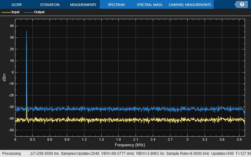
The input contains two sinusoidal signals each with a frame length of 1024. The first sinusoidal signal contains a tone at 200 Hz. The second sinusoidal signal contains a tone at 4 kHz.
frameLen = 1024;
sin_200Hz = dsp.SineWave(Frequency=200,SampleRate=Fs, ...
    SamplesPerFrame=frameLen);
sin_4KHz = dsp.SineWave(Frequency=4e3,SampleRate=Fs, ...
    SamplesPerFrame=frameLen);
Initialize a spectrumAnalyzer object to view the spectrum of the input and the filtered output.
specScope = spectrumAnalyzer(SampleRate=Fs,PlotAsTwoSidedSpectrum=false, ...
    ChannelNames={'Input','Output'},ShowLegend=true);
Stream in 1e3 frames of the noisy input sinusoidal signal. The input noise is white Gaussian with a mean of 0 and a variance of 0.01. Pass the signal through the designed filter. Visualize the spectrum of the input and output signals in spectrum analyzer.
for idx = 1:1e3
    x = sin_200Hz()+sin_4KHz()+0.01*randn(frameLen,1);
    y = mimoFilt(x);
    specScope([x,y])
end