How Is a Moving Average Filter Different from an FIR Filter?
The moving average filter is a special case of the regular FIR filter. Both filters have finite impulse responses. The moving average filter uses a sequence of scaled 1s as coefficients, while the FIR filter coefficients are designed based on the filter specifications. They are not usually a sequence of 1s.
The moving average of streaming data is computed with a finite sliding window:
N + 1 is the length of the filter. This algorithm is a special case of the regular FIR filter with the coefficients vector, [b0, b1, ..., bN].
To compute the output, the regular FIR filter multiplies each data sample with a coefficient from the [b0, b1, ..., bN] vector and adds the result. The moving average filter does not use any multipliers. The algorithm adds all the data samples and multiplies the result with 1 / filterLength.
Frequency Response of Moving Average Filter and FIR Filter
Compare the frequency response of the moving average filter with that of the regular FIR filter. Set the coefficients of the regular FIR filter as a sequence of scaled 1's. The scaling factor is 1/|filterLength|.
Create a dsp.FIRFilter System object™ and set its coefficients to 1/40. To compute the moving average, create a dsp.MovingAverage System object with a sliding window of length 40. Both filters have the same coefficients. The input is Gaussian white noise with a mean of 0 and a standard deviation of 1.
filter = dsp.FIRFilter(Numerator=ones(1,40)/40);
mvgAvg = dsp.MovingAverage(40);
input = randn(1024,1);
filterOutput = filter(input);
mvgAvgOutput = mvgAvg(input);
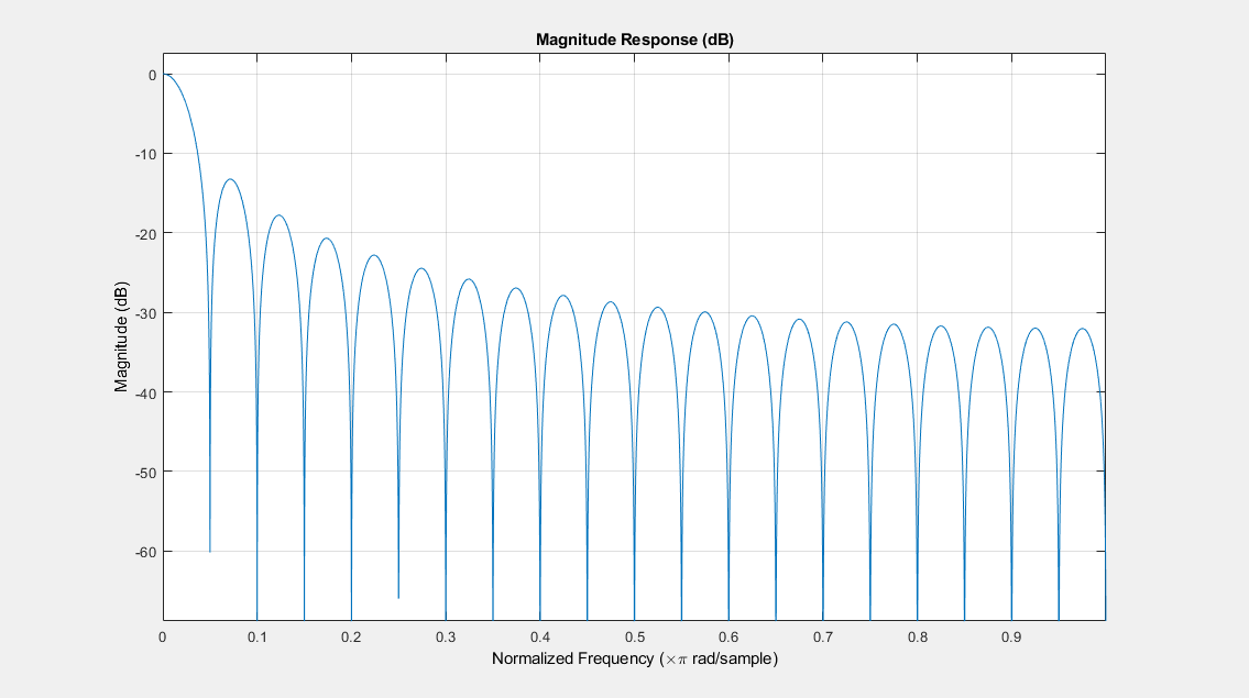
Visualize the frequency response of both filters. The frequency responses match exactly, which proves that the moving average filter is a special case of the FIR filter.
filterAnalyzer(filterOutput,1,mvgAvgOutput,1,...
    FilterNames=["FIRFilter","MovingAverageFilter"]);

For comparison, view the frequency response of the filter without noise.
filterAnalyzer(filter);

Compare the filter's frequency response to that of the ideal filter. You can see that the main lobe in the passband is not flat and the ripples in the stopband are not constrained. The moving average filter's frequency response does not match the frequency response of the ideal filter.
To realize an ideal FIR filter, change the filter coefficients to a vector that is not a sequence of scaled 1s. The frequency response of the filter changes and tends to move closer to the ideal filter response.
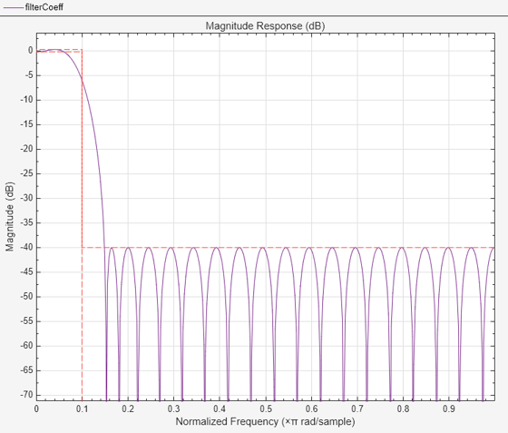
Design the filter coefficients based on predefined filter specifications. For example, design an equiripple FIR filter with a normalized cutoff frequency of 0.1, a passband ripple of 0.5, and a stopband attenuation of 40 dB. Use fdesign.lowpass to define the filter specifications and the design method to design the filter.
FIReq = fdesign.lowpass('N,Fc,Ap,Ast',40,0.1,0.5,40);
filterCoeff = design(FIReq,'equiripple',SystemObject=true);
filterAnalyzer(filterCoeff)

The filter's response in the passband is almost flat (similar to the ideal response) and the stopband has constrained equiripples.