Multicore Code Generation for Dataflow Domain
R2026bThis example shows how to deploy a noise reduction application on multicore target hardware using a dataflow domain. The example generates multicore code for an ARM CPU in a Zynq hardware and measures performance using execution-time profiling.
For information about analyzing multicore execution behavior using the Multicore tab, see Multicore Analysis Using a Dataflow Domain.
Noise Reduction System
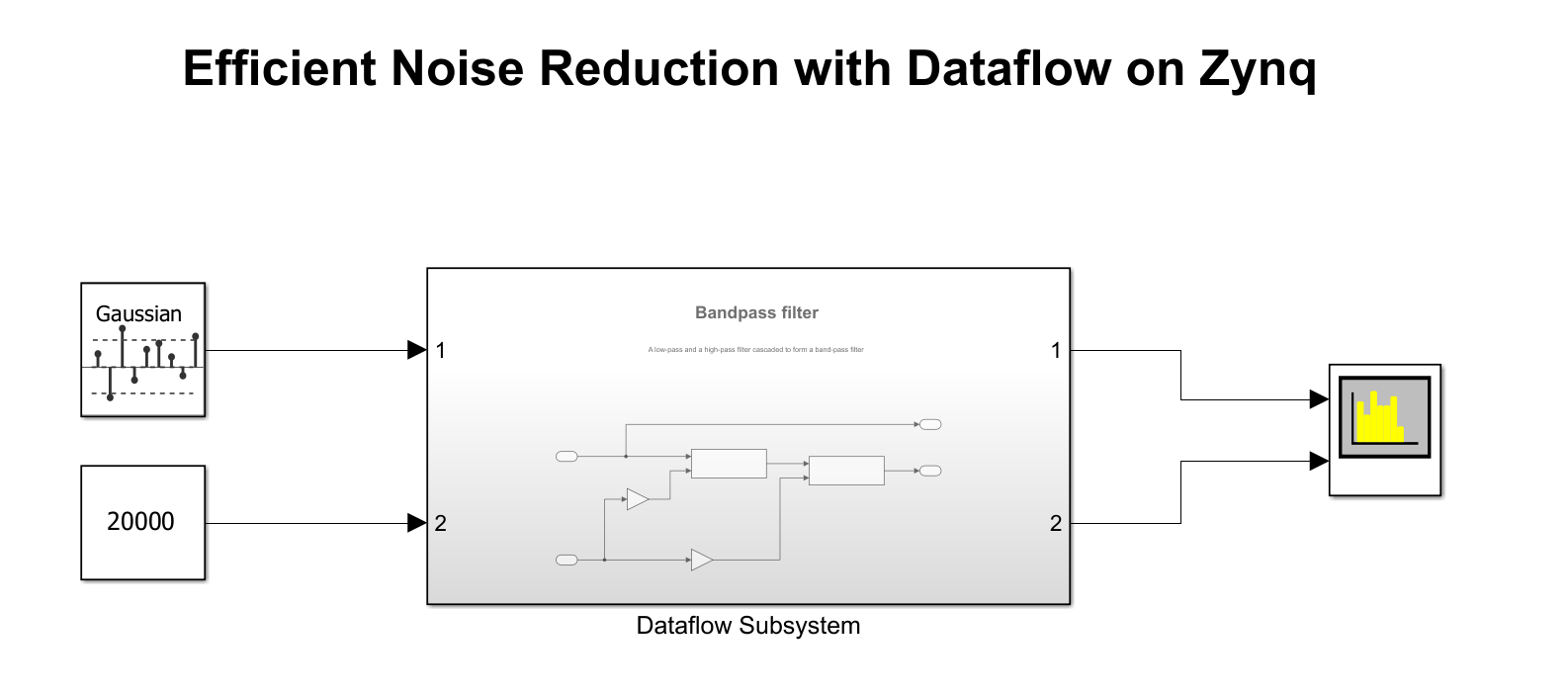
The model in this example uses two Variable Bandwidth IIR filter blocks configured as a low-pass and a high-pass filter respectively. The Dataflow Subsystem block connects the filters in series to form a bandpass noise filtering system. The source signal is a random noise.
Open the dataflowzynq model.
Configure Hardware Settings
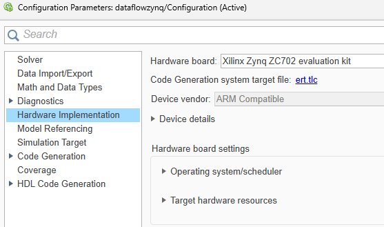
Configure the model to generate code for the Zynq-based hardware. This example uses a Zynq-7000 SoC ZC702 Evaluation Kit. To install the required support package, see Install Support for AMD FPGA and SoC Devices (SoC Blockset).
Specify Dataflow Execution Domain for Subsystem
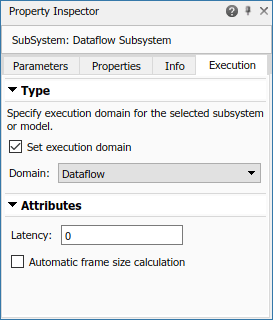
To specify dataflow as the execution domain for the subsystem, set the Domain parameter to Dataflow using the Property Inspector.
Select the subsystem and then select View > Property Inspector.
In the Property Inspector, select Set domain specification and then select
Dataflowfor the Domain parameter. You can also use the Dataflow Subsystem block from the Dataflow library of DSP System Toolbox™ to get a subsystem that is preconfigured with the dataflow execution domain.
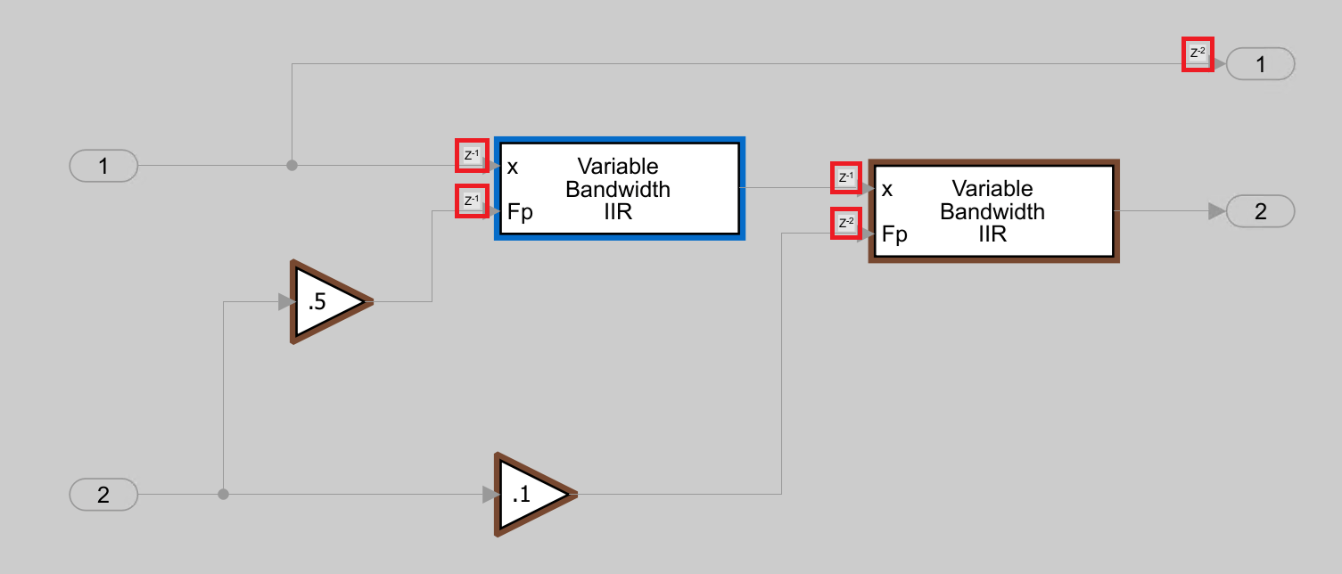
To increase the throughput of a system, you can increase the latency of a system. To modify the latency, specify the Latency value in the Execution tab of the Property Inspector. Setting a Latency value of 1 adds a pipeline delay to break dependency between the filter blocks and enable the dataflow domain to achieve concurrency.
Perform Multicore Analysis
When you specify the dataflow execution domain, the Multicore tab opens on the Simulink toolstrip.

On the Multicore tab, select a cost method to determine the execution cost of each block.
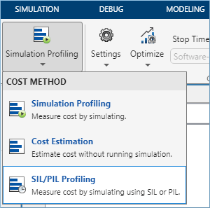
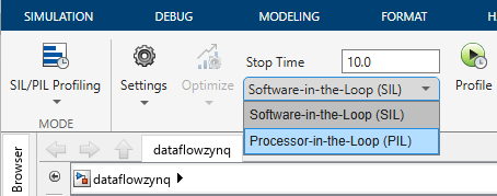
Select Processor-in-the-Loop (PIL) to measure cost values on the target hardware.
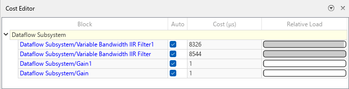
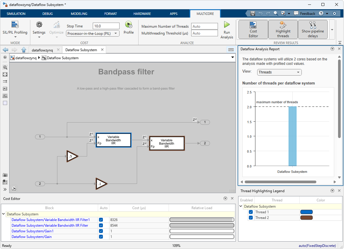
After profiling completes, the Cost Editor displays average execution time (cost) for each block in microseconds.
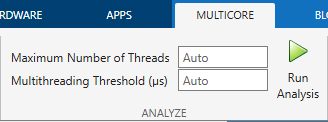
Click Run Analysis to partition the model for multicore execution.
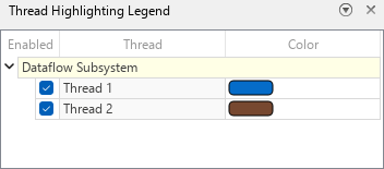
The analysis assigns blocks to threads. The Thread Highlighting Legend shows two threads, indicating that two parallel threads can execute the blocks inside the dataflow subsystem.
Multicore Code Generation of Dataflow Subsystem
To enable multicore code generation, on the Solver pane of the Configuration Parameters, under Solver details, select the Allow tasks to execute concurrently on target check box.
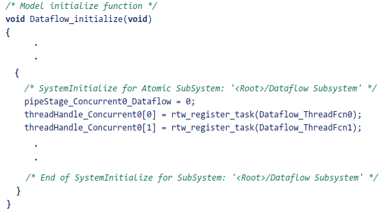
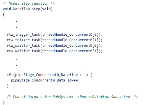
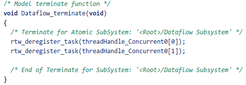
Build the Dataflow Subsystem block to generate multicore code. After code generation is completed, you can observe the generated functions for each concurrent thread created by the dataflow domain and how they are triggered during execution of the model step function.
The Dataflow Subsystem block generates two thread functions, Dataflow_ThreadFcn0 and Dataflow_ThreadFcn1.
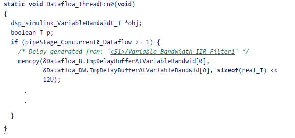
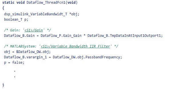
The thread functions are registered as POSIX threads at model initialization and triggered during each model step. The consecutive trigger and wait function calls implement the fork-join pattern for the dataflow threads.
Multicore Execution Performance
Simulate the model and measure the execution time of the multicore generated code on the target hardware.
Average execution time of generated code for single-core = 5.6 ms
Average execution time of generated code for multicore = 3.9 ms
Actual speedup with dataflow: 1.44x

