主要内容

Serial Peripheral Configuration

R2026b

Configure Serial Transmit block and Serial Receive block peripherals

Since R2026b

Description

Add-On Required: This feature requires the Embedded Coder Support Package for Infineon AURIX TC4x Microcontrollers add-on.

Configure the serial block peripherals and map them to the corresponding peripheral registers on the Infineon® AURIX™ Microcontroller board.

This mapping ensures that the generated code uses the intended hardware resources for serial communication and helps identify peripheral configuration conflicts before deployment.

Open the Serial Peripheral Configuration

Follow these steps to configure serial peripherals in the Hardware Mapping tool.

  1. To access the configuration parameters, in the model, on the Modeling tab, click Model Settings. In the Hardware Implementation pane, set Hardware board to Infineon AURIX TC4x.

  2. To open the Hardware Mapping tool, in the Simulink editor, on the Hardware tab, click Hardware Mapping.

    Hardware Mapping

  3. In the Mapping Browser pane:

    • To configure the serial peripherals, navigate to Peripherals > Serial.

    • To configure the serial transmit modules, navigate to Peripherals > Serial > Serial Transmit.

    • To configure the serial receive modules, navigate to Peripherals > Serial > Serial Receive.
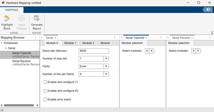
    Serial peripheral configuration in Hardware Mapping Tool

Parameters

expand all

Serial > Module n

Specify the baud rate for serial data communication.

Note

Communication at 9600 baud rate do not work while using FTDI-based USB-to-UART bridges because of clock tolerance differences between the AURIX baud rate generator and the external receiver. To improve communication reliability, configure a higher baud rate, such as 115200.

Specify the number of bit intervals that indicates the end of a data frame.

Specify parity bit type to detect single‑bit transmission errors. Select Disable if the transmitted data frame does not include a parity bit.

Specify the number of bits to transmit or receive in a serial data frame.

Select to configure serial data transmission parameters and events.

Select to configure serial data reception parameters and events.

Select to configure error events.

Serial > Module n > Transmission parameters

Select the pin number for serial data transmission.

Dependencies

To enable this parameter, select the Enable and configure Tx parameter.

Select the configuration mode of the serial transmit pin.

  • Push-pull — Actively drives the transmit pin to both high and low logic levels.

  • Open drain — Actively drives the transmit pin to low logic level and requires a pull-up resistor to achieve the high logic level.

Dependencies

To enable this parameter, select the Enable and configure Tx parameter.

Specify the number of bit periods during which the serial communication line remains idle between the transmitted frames.

Dependencies

To enable this parameter, select the Enable and configure Tx parameter.

Serial > Module n > Transmission events

Specify the priority level for servicing transmit events during serial communication.

Dependencies

To enable this parameter, select the Enable and configure Tx parameter.

Serial > Module n > Reception parameters

Select the pin number for serial data reception.

Dependencies

To enable this parameter, select the Enable and configure Rx parameter.

Select one of these configuration modes for the serial receive pin.

  • No-pull — Disables internal pull resistors.

  • Pull-up — Enables an internal pull-up resistor to provide a default high logic level on the receive pin when it is not driven.

  • Pull-down — Enables an internal pull-down resistor to provide a default low logic level on the receive pin when it is not driven.

Dependencies

To enable this parameter, select the Enable and configure Rx parameter.

Specify the number of times the receiver samples each incoming bit.

Dependencies

To enable this parameter, select the Enable and configure Rx parameter.

Specify the number of samples used to receive each serial data bit. Increasing the oversampling factor improves bit timing accuracy and noise immunity, but increases the required sampling clock frequency.

Dependencies

To enable this parameter, select the Enable and configure Rx parameter.

Specify the location within the oversampled bit period at which the receiver evaluates the incoming serial data. Select a value less than the oversampling factor value.

Dependencies

To enable this parameter, select the Enable and configure Rx parameter.

Specify the number of samples used to determine each received bit value. Select 1 for single sampling or 3 for majority vote sampling to improve noise immunity.

Dependencies

To enable this parameter, select the Enable and configure Rx parameter.

Serial > Module n > Reception events

Specify the priority level for receive events during serial communication.

Dependencies

To enable this parameter, select the Enable and configure Rx parameter.

Serial > Module n > Error events

Select to enable parity error event.

Dependencies

To enable this parameter, select the Enable error event parameter.

Select to enable frame error event.

Dependencies

To enable this parameter, select the Enable error event parameter.

Select enable overflow error of the receive FIFO register.

Dependencies

To enable this parameter, select the Enable error event parameter.

Select enable underflow error of the receive FIFO register.

Dependencies

To enable this parameter, select the Enable error event parameter.

Select enable overflow error of the transmit FIFO register.

Dependencies

To enable this parameter, select the Enable error event parameter.

Serial Transmit > Module selection

Specify the module for serial data transmission.

Serial Receive > Module selection

Specify the module for serial data reception.

Version History

Introduced in R2026b