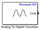
Analog To Digital Converter
Libraries:
Embedded Coder Support Package for Renesas RA Microcontrollers /
Renesas RA6 Based
Description
Use the Analog to Digital Converter block to convert the analog value at
an ADC input pin to a digital value. The block output is a 1-by-N row
vector depending on the number of conversions N. The block measures the voltage of an
analog pin relative to the analog input reference voltage on Renesas RA
Microcontrollers.
Examples
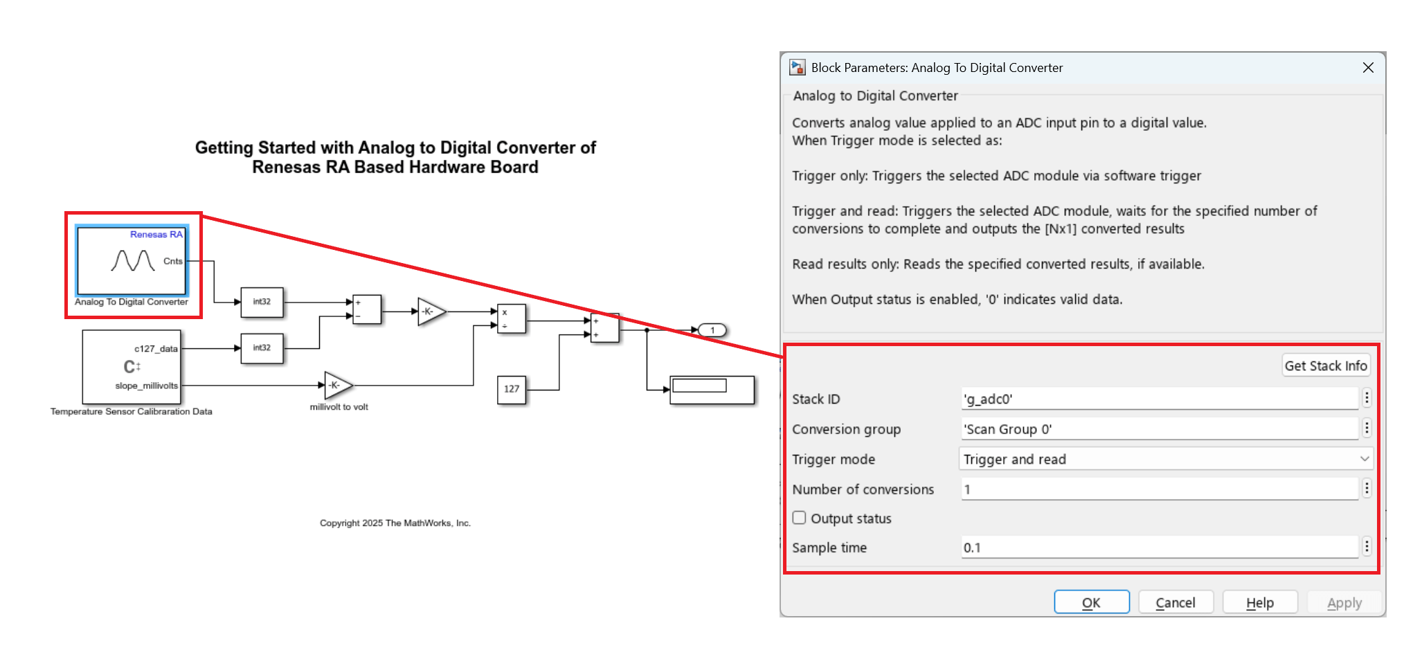
Using Analog to Digital Converter Block with Renesas RA Microcontrollers
Digitize analog signals on Renesas® RA microcontrollers using the Analog to Digital Converter (ADC) block in Simulink® with Embedded Coder® Support Package for Renesas RA Microcontrollers. In this example, you measure the on-chip temperature sensor on a Renesas MCK-RA6T2 board and convert raw ADC values into temperature readings.
Ports
Input
Convert analog signal on ADC input pin to digital signal.
Triggers the ADC input pin for conversion.
1- ADC start of conversion is triggered0- ADC start of conversion is not triggered
Dependencies
To enable this port, set the Trigger mode parameter
to Trigger only.
Data Types: Boolean
Output
The block outputs the digital values of selected analog channels converted
from Analog to Digital Converter (ADC) as a 1-by-N vector,
where N is number of conversions.
Dependencies
To enable this port, set the Trigger mode parameter
to either Trigger and read or Read results
only.
Data Types: uint16
The block outputs the ADC block status.
When the trigger mode is Trigger and Read or Read results only the block outputs the following status:
0- output counts are valid.1- output counts are not available or overrun flag is set.
When the trigger mode is Trigger only the block outputs the following status:
0- when ADC is triggered1- when ADC is not triggered
Dependencies
To enable this port, select the Output status parameter.
Data Types: int32
Parameters
Specify the unique identifier for the ADC stack to be used for conversion. This string links the Analog to Digital Converter block to a specific ADC hardware instance or configuration. Click Get Stack Info to retrieve the Stack ID from the linked RA Smart Configurator project, or specify it manually in character array format.
Programmatic Use
Block Parameter:
StackID
|
Specify the conversion group within the selected ADC module to be used for analog to digital conversions.
Programmatic Use
Block Parameter:
GroupId
|
Select how conversion is handled for this block. Some options trigger a new conversion, while option such as Read results only simply read the result of a previous conversion without starting a new one.
Trigger and read— Select this option to trigger ADC start of conversion at every sample time. The block output waits until the conversion is complete and emits the results. This option enables the output port Cnts.Trigger only— Use this option to trigger start of ADC conversion of specified conversion group with Stack ID and Conversion group in triggered or enabled subsystems. As the block does not show the conversion results in this mode, use another Analog to Digital Converter block with the Trigger mode parameter set to Read results only to display the conversion results.Read results only— Select this option to read converted data. Check the Output status port to determine data validity:0indicates a successful read; any nonzero value indicates an error. This option also enables the output port Cnts.
Programmatic Use
Block Parameter:
TriggerMode
|
Specify the number of conversions the ADC module should perform in one
operation. This value determines how many analog-to-digital conversion results
will be read and output by the block. The block will wait for the specified number
of conversions to complete before outputting the results as an array of size
[Nx1], where N is the number of
conversions.
Dependencies
To enable the Sample time parameter, set the
Trigger mode parameter to either Trigger
and read or Read results
only.
Programmatic Use
Block Parameter:
NumberOfConversions
|
When you select this parameter, the block configures Status output port. The Status port outputs the status of the ADC conversion.
Programmatic Use
Block Parameter:
OutputStatus
|
Specify how often (in seconds) the block reads the pin value. Enter a value greater than zero. When you specify this parameter as -1, Simulink® determines the best sample time for the block based on the block context within the model.
Dependencies
To enable the Sample time parameter, set the
Trigger mode parameter to either Trigger
and read or Read results
only.
Programmatic Use
Block Parameter:
SampleTime
|
Version History
Introduced in R2026a
MATLAB Command
You clicked a link that corresponds to this MATLAB command:
Run the command by entering it in the MATLAB Command Window. Web browsers do not support MATLAB commands.
选择网站
选择网站以获取翻译的可用内容,以及查看当地活动和优惠。根据您的位置,我们建议您选择:。
您也可以从以下列表中选择网站:
如何获得最佳网站性能
选择中国网站(中文或英文)以获得最佳网站性能。其他 MathWorks 国家/地区网站并未针对您所在位置的访问进行优化。
美洲
- América Latina (Español)
- Canada (English)
- United States (English)
欧洲
- Belgium (English)
- Denmark (English)
- Deutschland (Deutsch)
- España (Español)
- Finland (English)
- France (Français)
- Ireland (English)
- Italia (Italiano)
- Luxembourg (English)
- Netherlands (English)
- Norway (English)
- Österreich (Deutsch)
- Portugal (English)
- Sweden (English)
- Switzerland
- United Kingdom (English)

