Using Analog to Digital Converter Block with Renesas RA Microcontrollers
This example shows how to digitize analog signals on Renesas® RA microcontrollers using the Analog to Digital Converter (ADC) block in Simulink® with Embedded Coder® Support Package for Renesas RA Microcontrollers. In this example, you measure the on-chip temperature sensor on a Renesas MCK-RA6T2 board and convert raw ADC values into temperature readings.
This example runs generated code on the Renesas RA Microcontroller. ADC configuration is defined in the Renesas RA Smart Configurator and referenced by the Simulink model during code generation.
Prerequisites
Before you begin,
Complete these tutorials:
Review the MCB-RA6T2 User's Manual.
Complete the Hardware Setup for Embedded Coder Support Package for Renesas RA Microcontrollers.
Required Hardware
To run this example you need the following hardware:
Renesas MCK-RA6T2 board
USB to Type-C cable
USB to Serial Converter
Micro USB cable
Configure ADC Block to Read On-chip Temperature Sensor
Configure the Analog to Digital Converter block to sample the on-chip temperature sensor on a Renesas MCK-RA6T2 board and provide the converted temperature available to a Simulink model. This workflow demonstrates a software-triggered ADC configuration that aligns ADC conversion with the model step size.
Open the Model
Open the
ra6t2_adc_gettingstartedexample model.
modelName = "ra6t2_adc_gettingstarted";
open_system(modelName)
This example model is configured to read ADC results during each model step and display the converted temperature value.
Configure Renesas RA Smart Configurator Project
The Renesas RA Smart Configurator defines how the ADC hardware operates. The ADC block in Simulink references this configuration during code generation, so the hardware settings must match the intended sampling.
Create a new Renesas RA Smart Configurator project or open an existing project associated with the model, and then launch it in the Renesas RA Smart Configurator tool.
1. Launch the Renesas RA Smart Configurator project in the Renesas RA Smart Configurator tool. For more information, see Getting Started with Renesas RA Microcontroller Boards.
2. Enable and configure channels to digitize temperature in the RA Smart Configurator project associated with model.
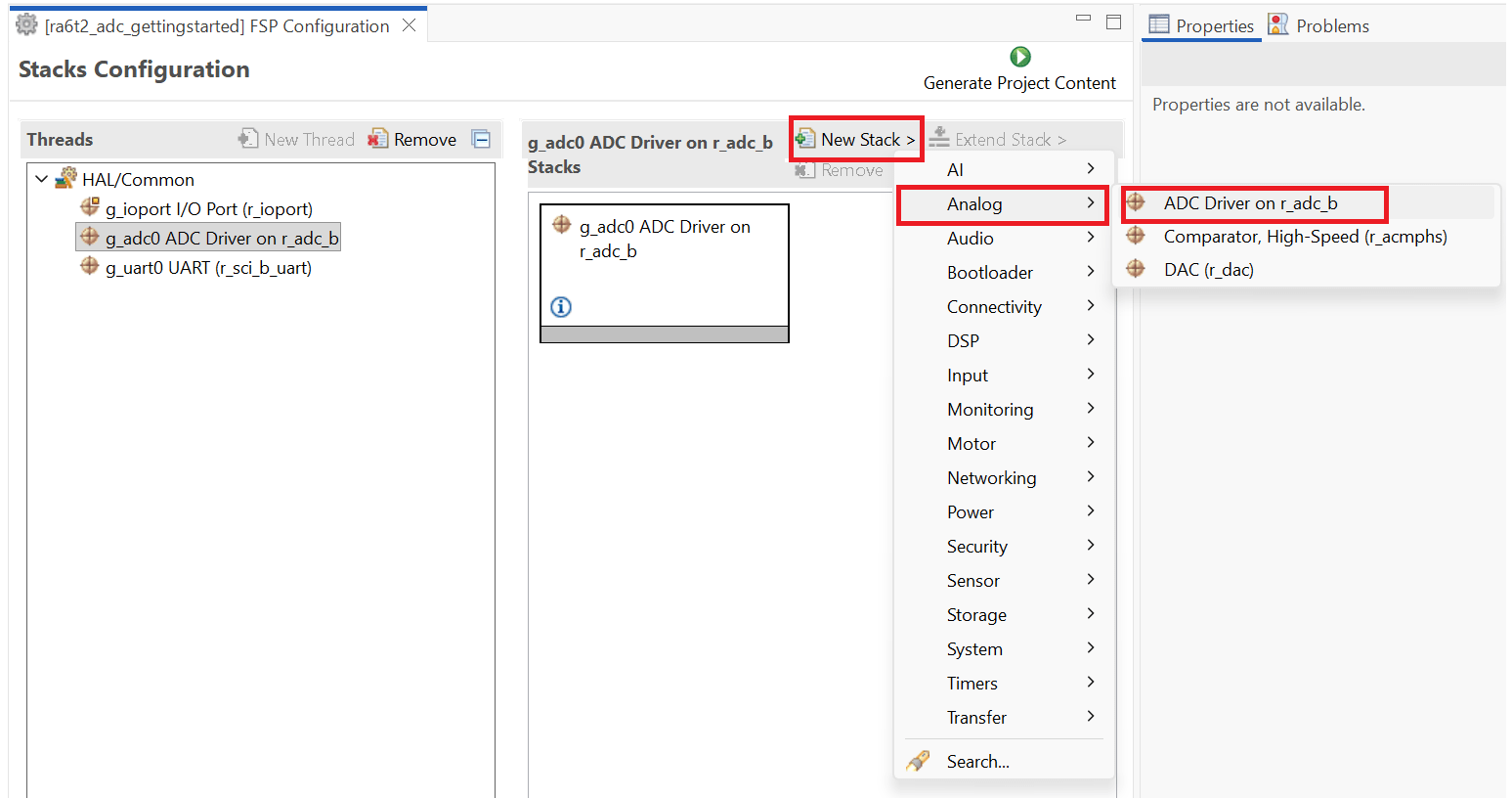
Use an existing
r_adc_bstack from the project or add a new one as shown in the screen below.
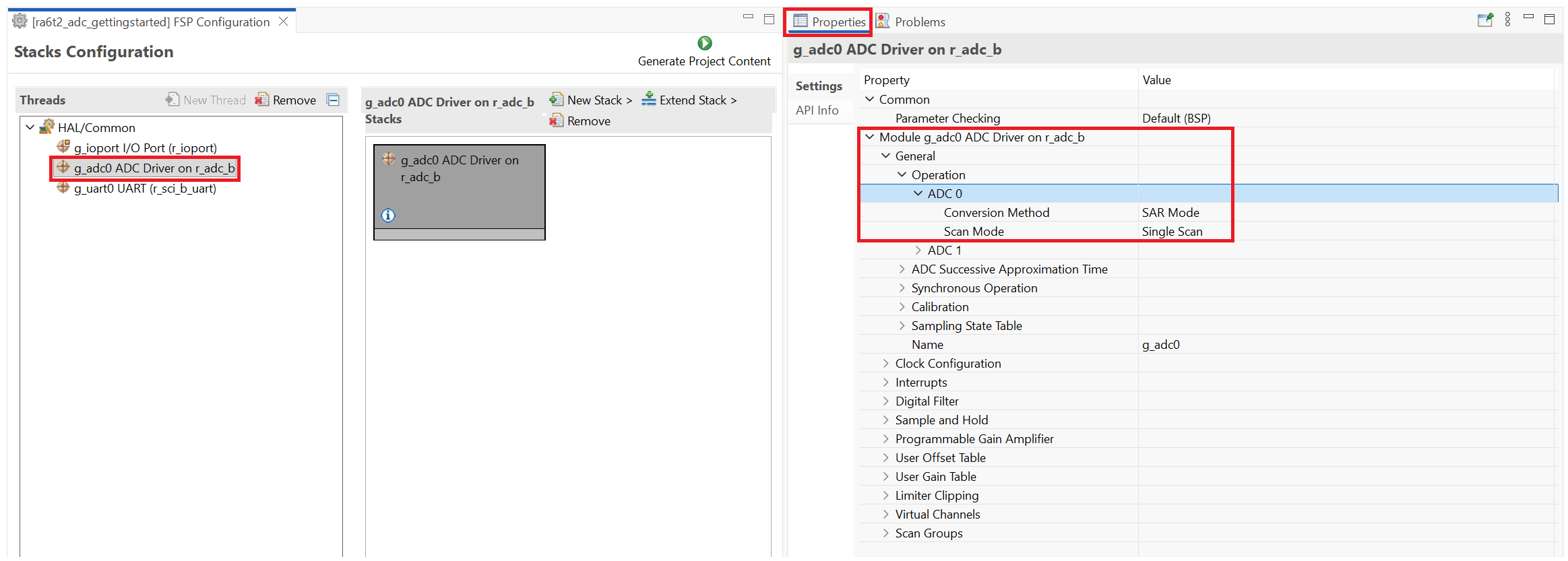
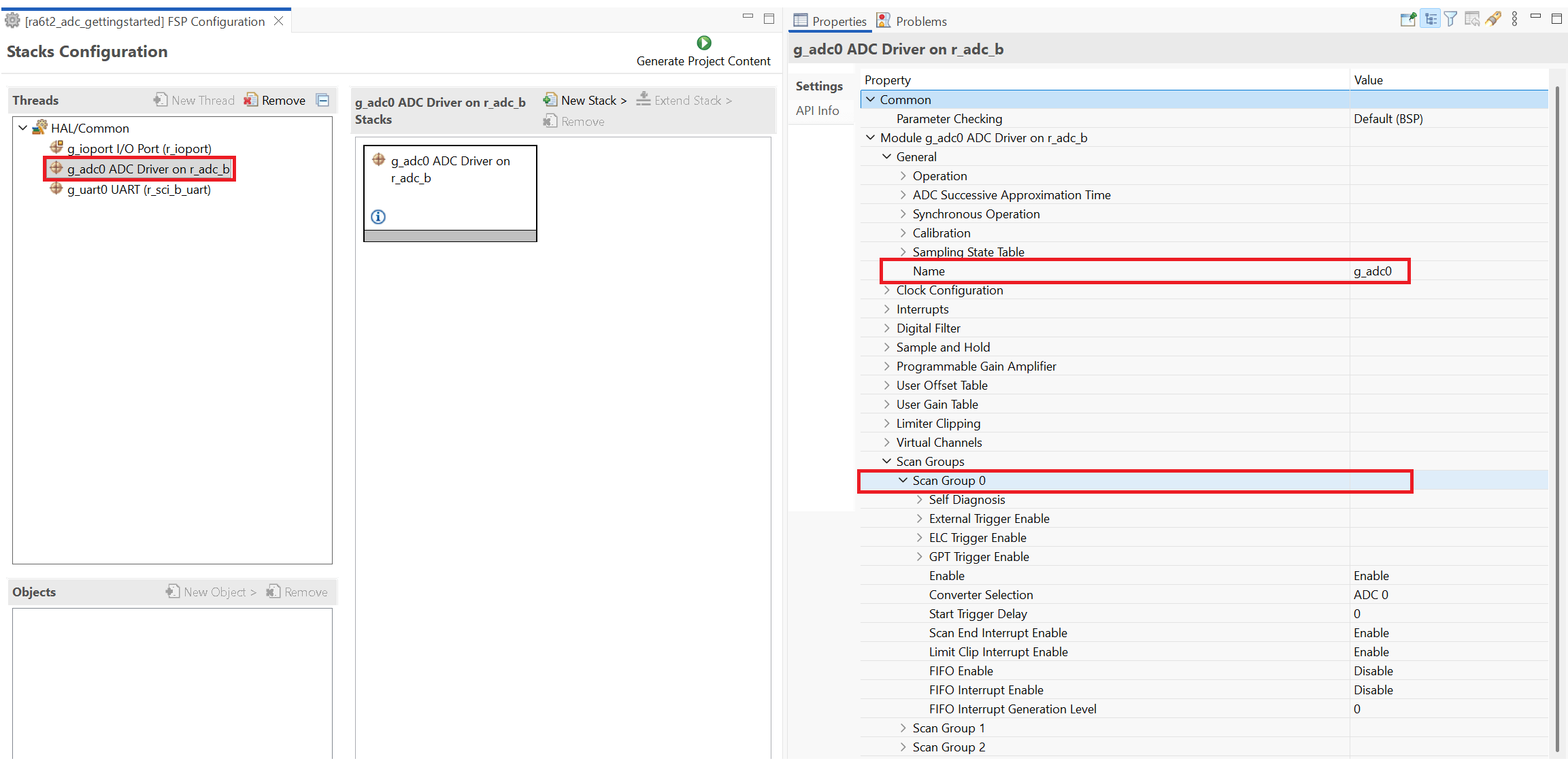
3. In this example, the Temperature channel is assigned to ADC 0 and sampled using Scan Group 0. This configuration ensures that the internal temperature sensor is included in the ADC scan sequence. Configure the Temperature channel under Scan Group 0.
Navigate to General > Operation > ADC 0 and set the Conversion Method to SAR mode and the Scan Mode to Single Scan.
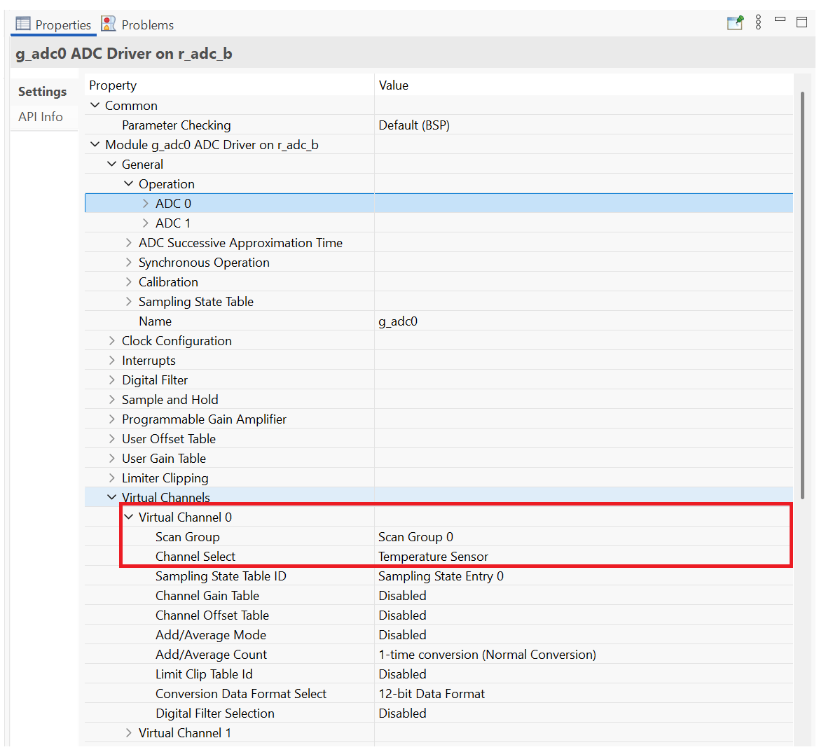
4. In Virtual Channels, configure Virtual Channel 0 to sample the Temperature channel.
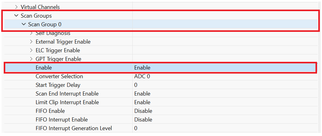
5. In Scan Groups, enable Scan Group 0, and then save the RA Smart Configurator project.
6. Double-click the ADC block to open its Block Parameters dialog box and configure the block to trigger and read ADC conversions at each model step. This configuration ensures consistent temperature measurements in the generated code.
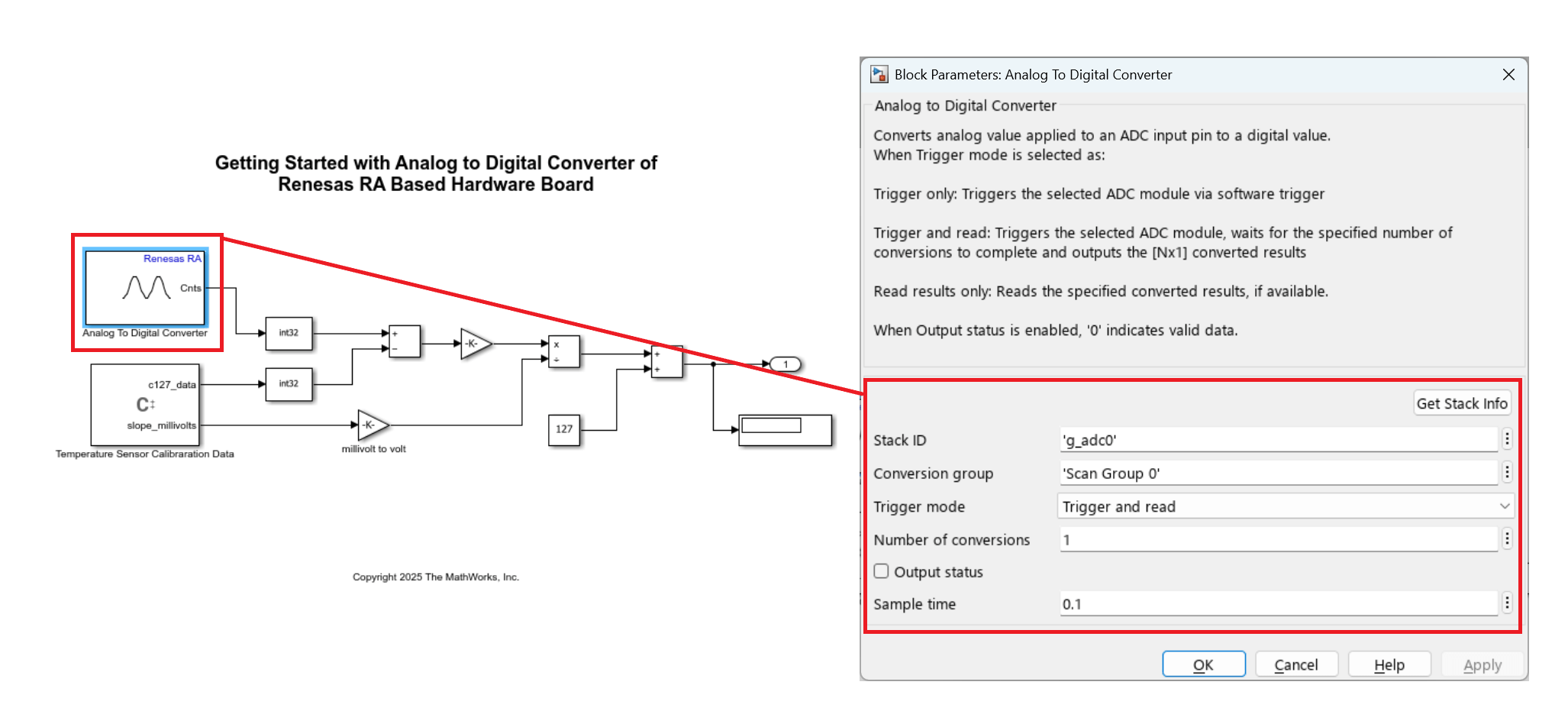
Select the correct
r_adc_bstack by clicking Get Stack Info or by manually selecting the stack from the associated RA Smart Configurator project.
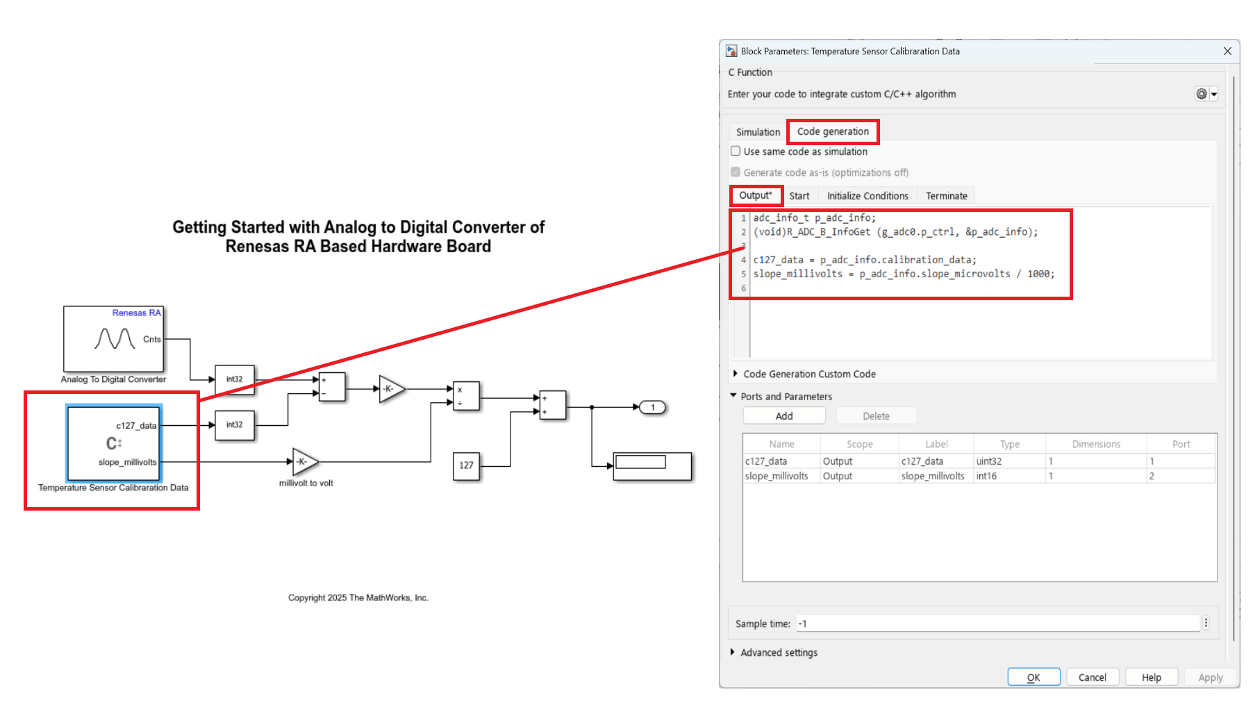
7. Use a C Caller block to read the reference temperature data stored in the board memory at 127 °C and compute the actual temperature according to the device reference manual. Access the calibration parameters through Renesas FSP APIs within the C Caller block so that the generated code applies the correct temperature conversion.
8. On the Hardware tab, click Monitor & Tune to execute the model on the hardware.
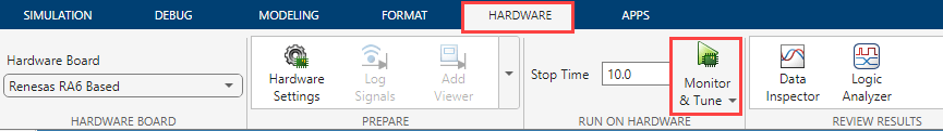
Observe the real-time converted temperature data in the Display block.
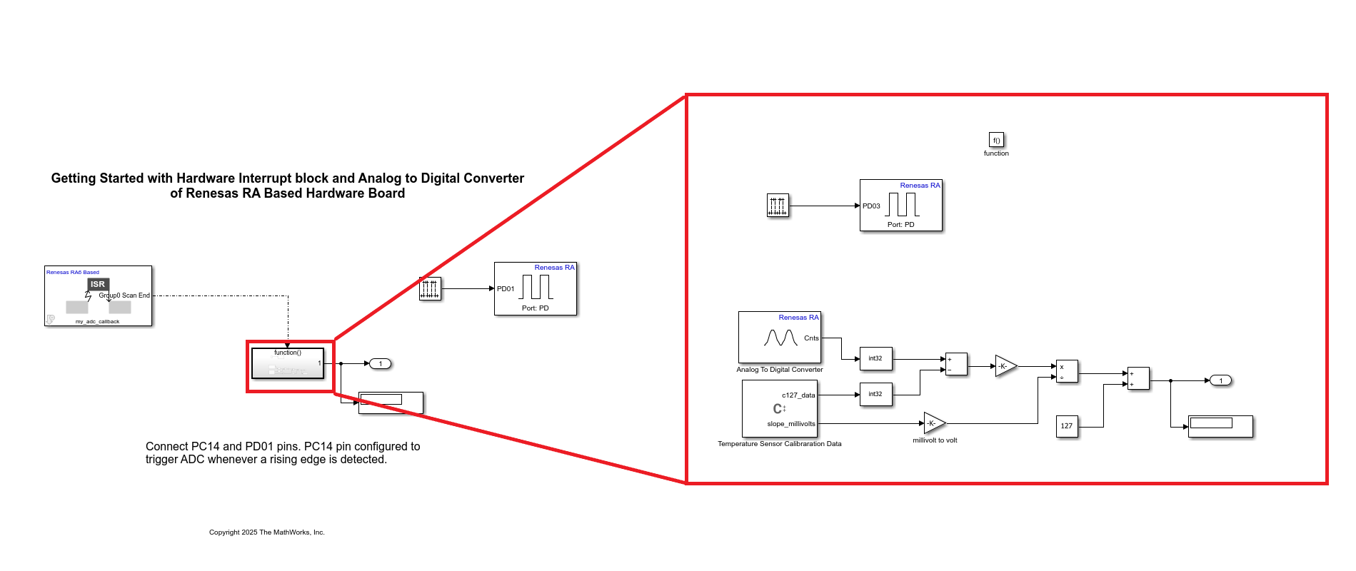
Read Temperature Using Hardware Interrupt and ADC Blocks
This section shows how to configure the Analog to Digital Converter block to output temperature data on the MCK-RA6T2 board at the end of each conversion and use a Hardware Interrupt block to process the results in real time.
In this approach, an external trigger starts the ADC conversion, and a Hardware Interrupt block executes the temperature conversion algorithm when Scan Group 0 completes a conversion. Running the algorithm inside the interrupt callback minimizes delay between sampling and computation.
Open the Model
modelName = "ra6t2_adc_hwi_gettingstarted";
open_system(modelName)
This model configures the ADC to trigger from an external source and processes conversion results inside a hardware interrupt.
Configure External ADC Trigger
To start ADC conversion based on a hardware event, configure an external trigger in the Renesas RA Smart Configurator project.
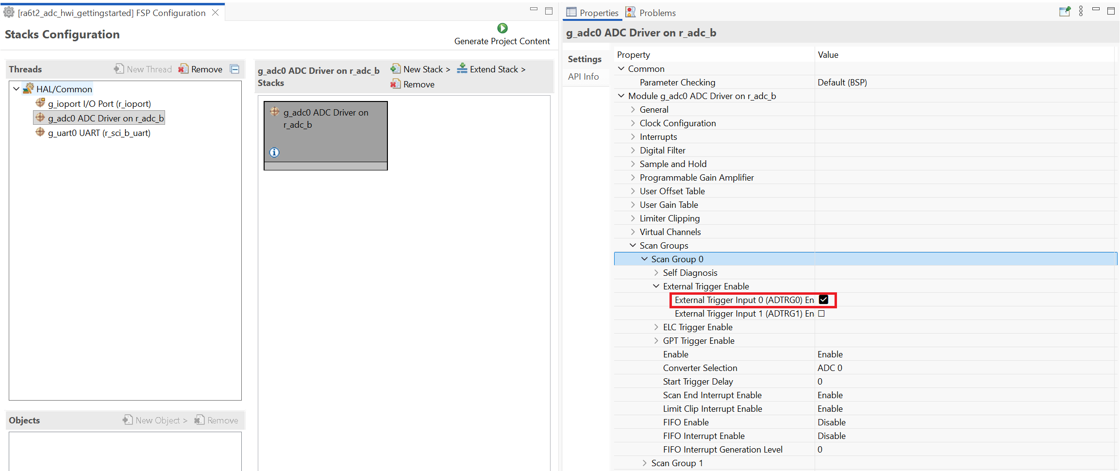
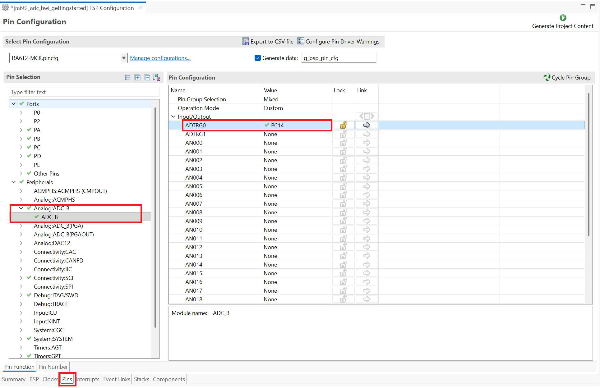
In the RA Smart Configurator project, enable ADTRG0 under Scan Groups > Scan Group 0 > External Trigger Enable. ADTRG0 maps to pin PC14. The ADC starts a conversion on the rising edge at this pin.
To generate the trigger signal, connect pin PD01 to PC14 using a hard wire. In the model, a Pulse Generator block drives PD01 at 1 Hz, creating a periodic external trigger for the ADC.
With this configuration, the board indicates system activity during execution: the LED connected to PD01 blinks at 1 Hz, and a second LED reflects ADC conversion activity.
The following table lists the block parameter settings and their corresponding selections in the RA Smart Configurator project.
Task | Remarks | Driver Block Parameters | RA Smart Configurator Project Settings |
|---|---|---|---|
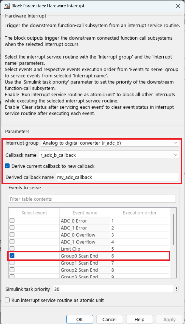
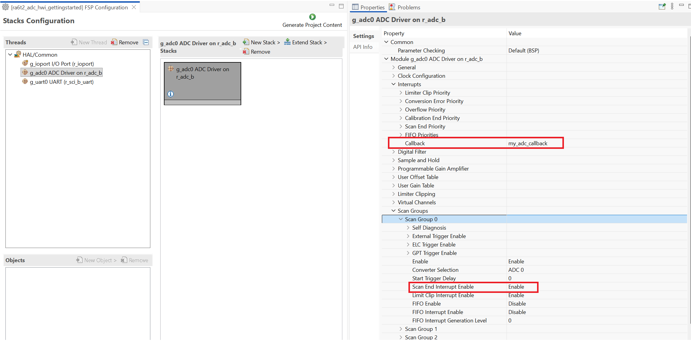
Hardware Interrupt block | The Derived callback name in the Hardware Interrupt block must match the name specified in the RA Smart Configurator project. |
|
|
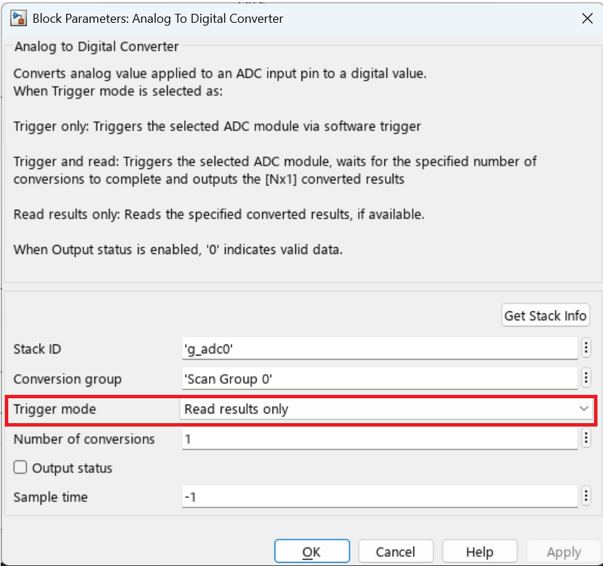
Analog to Digital Converter block | - In the RA Smart Configurator project, enable External Trigger. - In the Trigger mode drop-down list, select Read results only to ensure that the ADC returns values only when triggered by the external source ADTRG0. |
| - Enable trigger source
- External trigger pin PC14 configuration
|