Getting Started with Renesas RA Microcontroller Boards
This example shows how to use the Embedded Coder ® Support Package for Renesas® RA Microcontrollers to deploy and simulate a Simulink® model on hardware based on Renesas RA microcontrollers. With this support package, you can access hardware peripherals at run time using Simulink® blocks and configure those peripherals through the Renesas RA Smart Configurator tool.
In this example, you will configure a Simulink model with both single and varying sample rates, generate code, and verify operation by blinking LED1 indicator on a Renesas MCB-RA6T2 board.
Prerequisites
Before you begin,
Complete these tutorials:
Review the MCB-RA6T2 User's Manual.
Complete the Hardware Setup for Embedded Coder Support Package for Renesas RA Microcontrollers.
Required Hardware
USB Cable
Link a Renesas RA Smart Configurator Project to Your Simulink Model
Use the Renesas RA Smart Configurator to set up on-chip peripherals for your Simulink model. The Renesas RA Smart Configurator is a graphical desktop application that enables you to configure on-chip peripheral drivers, middleware, and board support packages for Renesas RA MCUs. Based on your configuration, it automatically generates the necessary driver code. You can create a new configuration or use an existing one. For more information, see RA Smart Configurator.
To link a Smart Configurator project to your Simulink model:
Open the
ra6t2_gettingstarted.slxSimulink model.
openExample("renesasra/GetStartedRenesasRABoardExample","supportingFile","ra6t2_gettingstarted")
2. In the Simulink model, go to Modeling > Model Settings (Ctrl+E) to open the Configuration Parameters dialog box.
3. Navigate to Hardware Implementation > Hardware board and then select Renesas RA Based board.
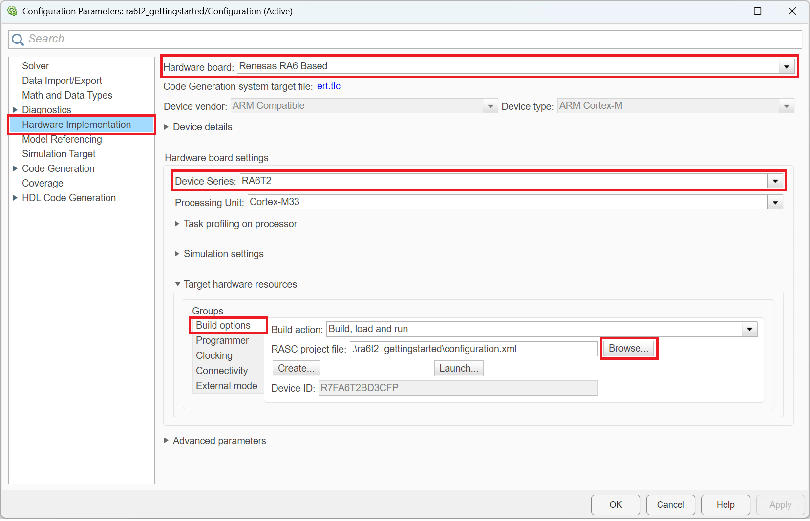
4. Go to Build options and click Browse to select an existing Renesas RA Smart Configurator project file. To create a new project, click Create.
5. If creating a new project:
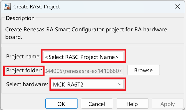
Specify a project name (avoid spaces).
Choose a folder to save the project.
Select the appropriate Renesas RA hardware
Click Apply and then OK.
Your Simulink model now links to a Smart Configurator project, enabling peripheral configuration and code generation for your board.
Blink LED1 at a Single Rate
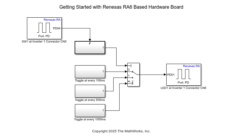
Configure the model to blink the LED1 indicator (connected to the PD01 pin at connector CN5 on the inverter board) at a single sample rate that you specify within the model.
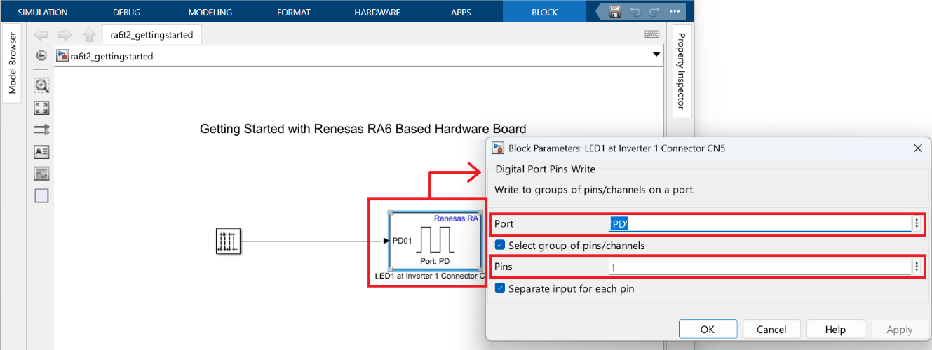
In the ra6t2_gettingstarted Simulink model, double-click the Digital Port Pins Read block to open the block parameter dialog box.
Set the pin according to the MCB-RA6T2 User's Manual: pin 1 of Port D (PD01) connects to LED1 near Connector CN5.
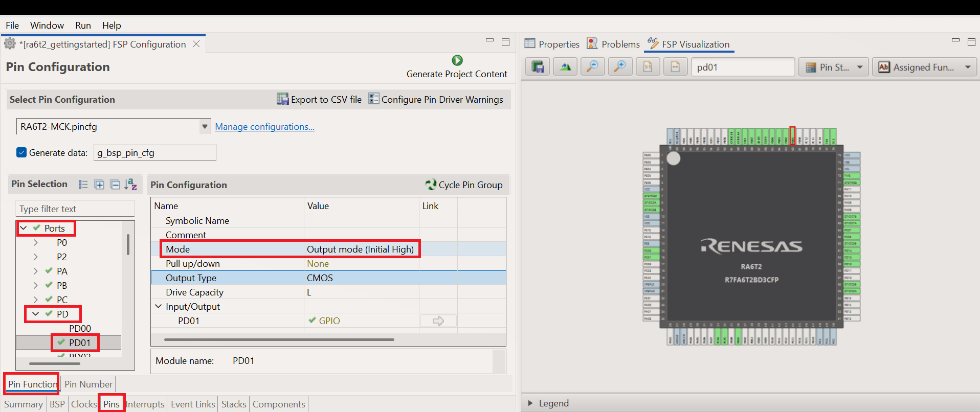
3. In the Smart Configurator project, set pin 1 of Port D as Output to enable toggling the LED. For information on creating or using existing RA Smart Configurator project, see Configure Peripherals Using Renesas RA Smart Configurator.
4. Generate and deploy code. Press Ctrl+B or click Build, Deploy & Start in the Simulink model.
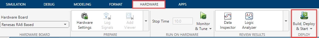
5. Monitor the build process by opening the Diagnostic Viewer through the link at the bottom of the model canvas. After deployment, verify that LED1 blinks, confirming the code runs on the hardware.
LED1 (located near connector CN5 on the board) should blink at a steady rate.
Blink LED1 at Varying Rates (Multitasking)
You can also configure the model to blink the LED at varying rates, using multiple sample rates in Simulink.
To blink the LED at varying rates:
Open the ra6t2_multitasking_gettingstarted Simulink model.
openExample("renesasra/GetStartedRenesasRABoardExample","supportingFile","ra6t2_multitasking_gettingstarted")
2. In the Simulink model, navigate to Modeling > Model Settings (Ctrl+E) to open Configuration Parameters dialog box.
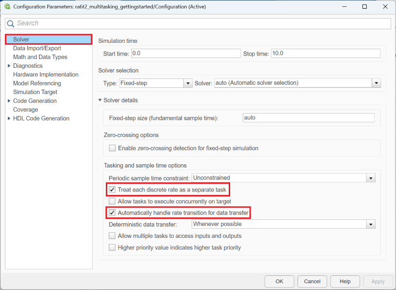
3. Click Solver and select Treat each discrete rate as separate task and Automatically handle rate transition for data transfer options.
4. Configure the blocks.
Double-click each block to set parameters.
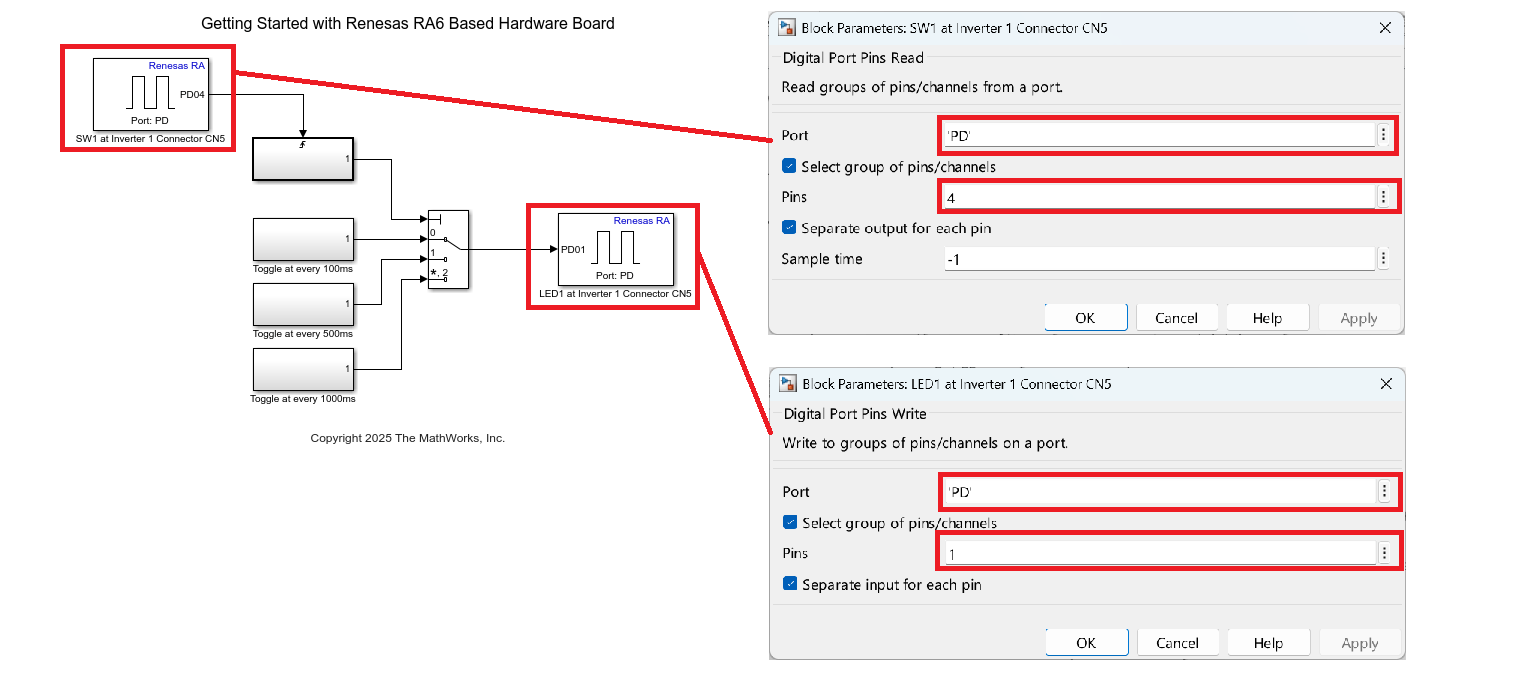
The User switch (SW1) connects to PD04 (Port D, Pin 4) at connector CN5 on the inverter, not directly on the MCB-RA6T2 board.
LED1 connects to Pin 1 of Port D (PD01).
5. In the Smart Configurator project, set PD04 as Input for SW1 and PD01 as Output for LED1. For information on configuring RA Smart configuration tool, see Configure Peripherals Using Renesas RA Smart Configurator. For information on configuring pin in the single rate model, see Blink LED1 at a Single Rate.
6. Generate and deploy code as before. After loading the code, LED1 blinks at varying rates, as defined in your model.

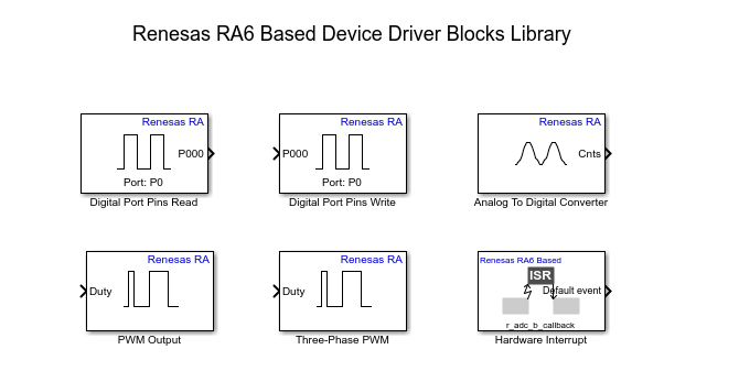
Explore the Block Library
The Embedded Coder Support Package provides Simulink blocks for Renesas RA peripherals. You can use these blocks to interact with sensors and actuators on your board.
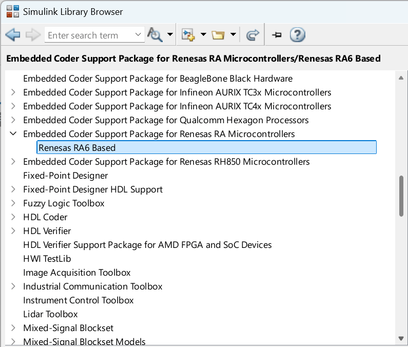
To browse available blocks, run this command in MATLAB:
slLibraryBrowser
In the Simulink Library Browser, navigate to Embedded Coder Support Package for Renesas RA Microcontrollers.
Other Things to Try
Try reading the switch (SW1) at slower rates and observe how the system responds.