Model Configuration Parameters
Model configuration parameters control model behaviour, simulation, code optimizations, interfaces, code style, build options, and other aspects of the generated code. When you create a new model, it contains the default configuration set that specifies the default values for the model configuration parameters. You can view and update the configuration parameters by following these steps.
Hardware Implementation Pane Overview
Default Hardware Implementation Pane
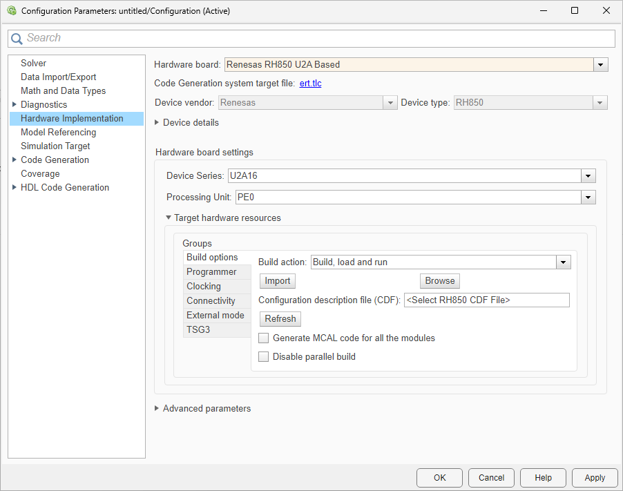
Configure hardware board to run Simulink® models.
In the Simulink Editor, select Modeling > Model Settings.
In the Configuration Parameter dialog box, click Hardware Implementation.
Set the Hardware board parameter to
Renesas RH850 U2A Based.The parameter values under Hardware board settings are automatically populated to their default values.
You can optionally adjust these parameters for your particular use case.
To apply the changes, click Apply.
For more information on selecting a hardware support package and general configuration settings, see Hardware Implementation Pane.
Hardware Board Settings
| Parameter | Description | Default Value |
|---|---|---|
Select the device series for the Renesas RH850 U2A Based hardware board. |
| |
| Select the processor unit for the device series. |
|
Task Profiling on Processor
| Parameter | Description | Default Value |
|---|---|---|
Display task profiling results in Simulink Data Inspector. |
| |
Save profiling results to a file. |
| |
Overwrite the profiling file if it exists. |
|
Simulation Settings
| Parameter | Description | Default Value |
|---|---|---|
Enable to set a seed value for the random number generator. |
| |
| Specify the seed value for the random number generator. |
| |
Enable to cache input data at the start of each task. |
| |
Specify the project folder for simulation data and files. |
| |
Browse to select the CDF folder. |
Build options
| Parameter | Description | Default Value |
|---|---|---|
Defines how Embedded Coder® responds when you build your model. |
| |
Select the Configuration description file (CDF). |
| |
| Import | Click Import to import a CDF file. | |
| Browse | Browse to select the CDF file. | |
| Refresh the configuration file. | ||
Generate MCAL code for all modules. | Off | |
| Disable parallel build | Disable parallel build for code and driver sources. | Off |
Programmer
| Parameter | Description | Default Value |
|---|---|---|
Select the programming interface. |
| |
Automatically selects the hardware. |
| |
| Select the hardware. | ||
| Refreshes the list of available hardware. |
Clocking
| Parameter | Description | Default Value |
|---|---|---|
Select the CDF arxml file to configure MCU clock settings. |
| |
Displays the main system clock frequency for the CPU. Requires selection of CDF arxml file. | Select CDF arxml file in Build Options | |
Displays the high speed peripheral clock frequency (CLK_HSB). Requires CDF arxml file selection. | Select CDF arxml file in Build Options |
Connectivity
External Mode
| Parameter | Description | Default Value |
|---|---|---|
Sets the transport layer used to exchange data between host and hardware. |
| |
Sets to view external mode execution progress and updates. |
| |
Automatically set the number of bytes to preallocate for the buffer in the hardware during simulation. |
| |
| Logging buffer size (in bytes) | Specify the memory buffer size for XCP-based External mode simulation. | 1000 |
| Maximum number of contiguous samples | Set the maximum number of contiguous samples for data logging in external mode. | 8 |
TSG3
| Parameter | Description | Default Value |
|---|---|---|
Enables configuration options for TSG30. |
| |
Sets the operating mode for TSG3. |
| |
Selects the event that triggers ADC sampling. |
| |
Selects the event for updating the duty cycle. | Valley | |
| Selects the event for reloading the duty cycle counter. | Valley | |
| Sets the carrier frequency for PWM generation. | 8 | |
| Sets the duty ratio for U phase as a percentage. | 50 | |
| Sets the duty ratio for V phase as a percentage. | 50 | |
| Sets the duty ratio for W phase as a percentage. | 50 | |
| Sets the positive dead time in raw counter values. | 50 | |
| Sets the inverse dead time in raw counter values. | 50 | |
| Enables configuration options for TSG31. | Off | |
| Sets the operating mode for TSG3. | HT PWM | |
| Selects the event that triggers ADC sampling. | None | |
| Selects the event for updating the duty cycle. | Valley | |
| Selects the event for reloading the duty cycle counter. | Valley | |
| Sets the carrier frequency for PWM generation. | 8 | |
| Sets the duty ratio for U phase as a percentage. | 50 | |
| Sets the duty ratio for V phase as a percentage. | 50 | |
| Sets the duty ratio for W phase as a percentage. | 50 | |
| Sets the positive dead time in raw counter values. | 50 | |
| Sets the inverse dead time in raw counter values. | 50 |