Audio Output
Send processed audio samples to audio devices on STMicroelectronics STM32F746G/STM32F769I–Discovery board
Add-On Required: This feature requires the Embedded Coder Support Package for STMicroelectronics STM32 Processors add-on.
Libraries:
Embedded Coder Support Package for STMicroelectronics STM32 Processors /
STM32F746G-Discovery
Embedded Coder Support Package for STMicroelectronics STM32 Processors /
STM32F769I-Discovery
Description
The Audio Output block writes the processed audio data to the audio device (headphones or speakers) that are connected to the processor on the STM32F746G/STM32F769I–Discovery™ board.
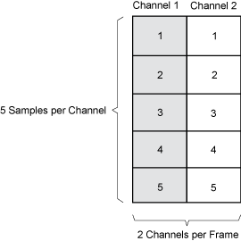
The block accepts int16 Pulse Code Modulated (PCM) audio frames. For
STM32F746G, these frames are either mono: ([1xN] or
[Nx1]) or stereo: ([2xN] or
[Nx2]) int16 matrix. For STM32F769I, these
frames are quad: [4xN] or [Nx4].
N is the number of samples per frame from the input signal, and
2 and 4 are the number of audio channels per
frame.
You can send audio samples at different rates, such as 8 kHz, 11 kHz, 16 kHz, 22 kHz, 32 kHz, 44 kHz, 48 kHz, 96 kHz, and 192 kHz (STM32F746G only), with different sampling frequencies.
Using the parameters of this block, you specify the device to which you want to send the audio. You also specify the volume level at which the block emits audio frames.
Write Audio to Headphone or Speaker
The STM32F746G–Discovery board sends audio to audio devices, headphones or speakers, or both, that are connected to it.
The int16 PCM audio frames from the input port of the Audio
Output block instance are streamed through the ARM®
Cortex® M7 processor and WM8994 codec. These frames are then sent to the
connected audio devices.
The audio data between the ARM Cortex M7 processor, WM8994 codec, and the audio devices are transferred by using I2S line.
Note
The audio frames streamed through the ARM Cortex M7 processor and WM8994 codec do not undergo any conversion.

Send Processed Audio Samples with Double Buffering
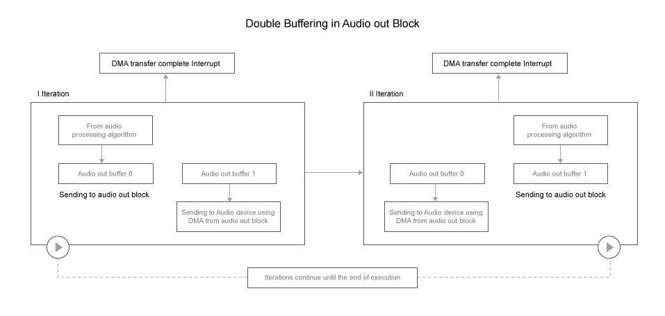
The Audio Output block uses a double buffering mechanism to send data to the audio device.
With double buffering, the DMA uses one buffer to transfer an audio frame from the processor to the audio device while the other buffer receives the processed audio frame from your audio algorithm. When sending the data to the audio device, doing so helps to prevent overwriting the buffer.
When you send an audio frame of length N samples, the block creates two
buffers of length N samples.
With the double buffering mechanism in theAudio Output block:
In the first iteration, when the processed audio signal is sent out to the audio device from Audio out buffer1, the Audio out buffer0 is filled with audio signal from the audio processing algorithm.
In the first iteration, the Audio out buffer1 does not contain the audio samples. Therefore, the audio samples from the Audio Output block are delayed by one audio frame. If your model has Audio Input and Audio Output blocks, there is a time delay of two audio frames. This delay occurs because the Audio Input block also uses the same double buffering technique.
After the DMA completes sending out the processed data from Audio out buffer1, an interrupt is generated.
In the second iteration, when the processed audio signal is sent out to the audio device from Audio out buffer0, the Audio out buffer1 is filled with the audio data from the audio processing algorithm.

Examples
Ports
Input
Parameters
More About
Extended Capabilities
Version History
Introduced in R2016b


