Parametric Audio Equalizer for STM32 Discovery Boards
This example shows how to model a three band parametric equalizer algorithm and run it on the ARM® Cortex®-M based STMicroelectronics® STM32 Discovery boards using Embedded Coder® Support Package for STMicroelectronics STM32 Processors.
The example is categorized into 2 workflows.
STM32CubeMX workflow
Available boards - STM32F4xx-based boards.
Legacy workflow
Available boards - STM32F4-Discovery, STM32F746G-Discovery, STM32F769I-Discovery and STM32F746G-Discovery
Support for the legacy workflow will be removed in a future release of MATLAB®
The blocks between the 2 workflows are not compatible with each other. For example, blocks from stm32discoverylib cannot be used in a model set with hardware boards of STM32F4xx Based.
Required Hardware
STM32F4xx-based board (CubeMX workflow) or STMicroelectronics STM32F4-Discovery or STM32F746G-Discovery board
Headphones
If using a STM32F4-Discovery, a USB TTL-232 adapter for Monitor and Tuning simulation
Prerequisites
We recommend completing:
STM32CubeMX workflow
Discovery boards (Legacy)
Available versions of this example:
Parametric Audio Equalizer for STM32F4xx based board using STM32CubeMX workflow
Parametric Audio Equalizer for STM32F4-Discovery (Support for the legacy workflow will be removed in a future release of MATLAB®)
Model
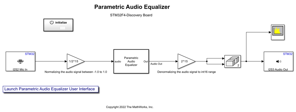
This example is an extension of the Parametric Audio Equalizer (DSP System Toolbox) example from the DSP System Toolbox™ that you can use to simulate the behavior of the audio algorithm on your hostparametric machine. Also refer to the Parametric Audio Equalizer for ARM Cortex-M Processor example that explains how to take advantage of the ARM Cortex-M Code Replacement Library (CRL) for DSP functions.
In this example, you will learn how to:
Set ARM Cortex-M CMSIS Code Replacement Library (CRL)
Use STM32F4-Discovery or STM32F746G-Discovery audio peripherals and schedule your algorithm based on audio DMA interrupts.
Note: Scheduling is not supported for STM32F4xx based board (CubeMX workflow)
Configure the Model for Simulation to tune parameters and watch live data when the application code is running on the STM32 Discovery Board.
Set ARM Cortex-M CMSIS Code Replacement Library (CRL)
The Embedded Coder Support Package for ARM Cortex-M Processors provides an optimized Code Replacement Library for signal processing and math operations.
You can refer to the Supported Simulink Blocks with CMSIS Library for ARM Cortex-M Processors and the Supported DSP System Toolbox Blocks with CMSIS Library for ARM Cortex-M Processors help pages in the Embedded Coder Support Package for ARM Cortex-M Processors for ARM documentation for more information.
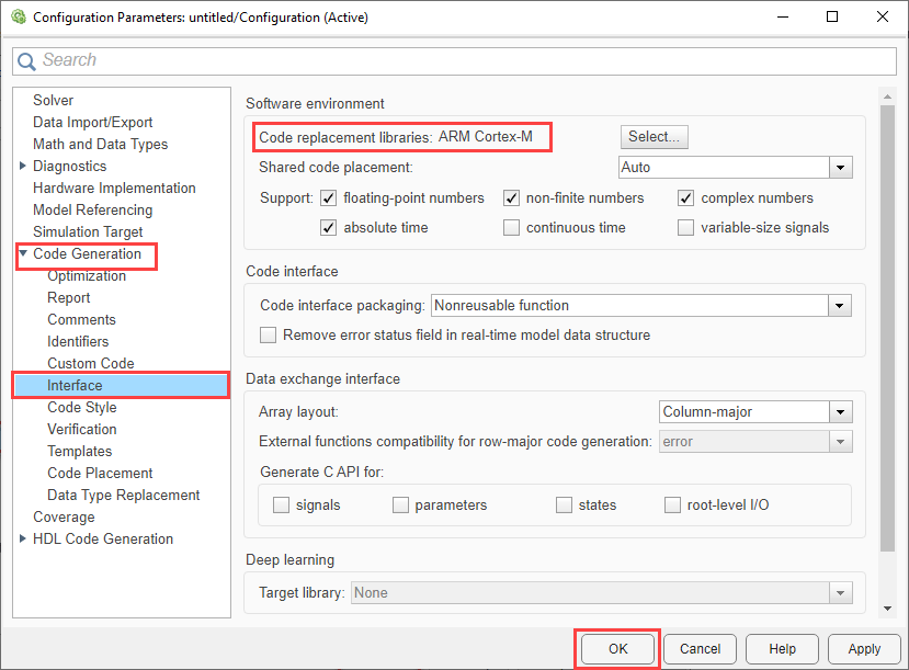
Open the Modeling tab and press CTRL+E to open Configuration Parameters dialog box. Go to Code Generation > Interface and select Code replacement library > ARM Cortex-M for the Parametric Audio Equalizer for STM32F4xx based board using STM32CubeMX workflow model:
STM32CubeMX Workflow
In the G.729 Voice Activity Detection for STM32F4xx based board example, the model uses a I2S Mic In block from the stm32blockslib to get audio data from the microphone. This block outputs a frame of 16-bit audio samples. The 'I2S Mic In' block is set with a sample frequency of 44.1kHz. The frame size is set to 441 audio samples to get a 10 millisecond audio frame.
The base rate trigger is automatically selected as the Audio Input in case of STM32F4xx based boards.
STM32 Discovery Boards (Legacy Workflow)
In the Parametric Audio Equalizer for STM32F4-Discovery example model and Parametric Audio Equalizer for STM32F746G-Discovery example model, the model uses a 'Mic In' block and 'Audio In' block from the STM32F4-Discovery library to get audio data from the microphone.
Use STM32F4-Discovery Audio Peripherals and Schedule Your Algorithm Based on Audio DMA Interrupts
In the Parametric Audio Equalizer for STM32F4-Discovery example model, the audio equalization is performed on audio data coming from the microphone available on the STM32F4-Discovery board. The model uses a 'Mic In' block from the STM32F4-Discovery library to get data from the microphone. This block outputs a frame of 16-bit audio samples.
The 'Mic In' block is set with a sample frequency of 44100Hz. The frame size is set to 44.1*20 to get a 20 ms audio frame containing 882 16-bit audio samples
Follow these steps to configure the Parametric Audio Equalizer for STM32F4-Discovery model:
1. Double click on the Mic In block to set the microphone Sample rate.
2. In the Block Parameters: Mic In dialog box, set audio frame to 20ms.

3. Double click on the Audio Out block to set the Audio out Sample rate. The 'Audio Out' block sample rate has to match the 'Mic In' block sample rate.

4. Ensure synchronization of all rates in the model.
a. Open the Modeling tab and press CTRL+E to open Configuration Parameters dialog box.
b. Go to Hardware Implementation > Operating system/scheduler and select Base rate trigger > "Mic In" block DMA interrupt..

5. To ensure "Mic In" block DMA interrupt as the Base rate trigger, the Mic In block has to be scheduled at the base rate. Open the Debug tab, select Information Overlays, and select Sample Time > Colors and make sure that the Mic In block shows in Red which indicates that it is scheduled at the base rate.

Note: You can also choose the "Audio Out" block DMA interrupt as the Base rate trigger in step 4. In this case, the "Audio Out" block should be scheduled at base rate. This will prevent the use of a faster rate in the model.
Use STM32F746G-Discovery Audio Peripherals
In the Parametric Audio Equalizer for STM32F746G-Discovery example model, the audio equalization is performed on a single channel audio data coming from the dual microphones available on the STM32F746G-Discovery board. The model uses a 'Audio In' block from the STM32F746G-Discovery library to get data from the microphone. This block outputs a frame of 2 * 16-bit audio samples. Hence a submatrix block is used in the model to extract a single channel and at the output stage the same channel is copied to the other channel.
The 'Audio In' block is set with a sample frequency of 44100Hz. The frame size is set to 44.1*20 to get a 20 ms audio frame containing 882, 2 channel 16-bit audio samples
Follow these steps to configure the Parametric Audio Equalizer for STM32F746G-Discovery model:
1. Double click on the Audio In block to set the microphone Sampling frequency.
2. In the Block Parameters: Audio In dialog box,set audio frame to 20ms.

3. Double click on the Audio Out block to set the Audio out Sampling frequency. The 'Audio Out' block sample rate has to match the 'Audio In' block sampling frequency.
4. In this example, the "Audio In" block DMA interrupt is automatically selected as the Base rate trigger for the model. This will ensure the synchronization of all rates in the model.
5. Open the Debug tab, select Information Overlays, and select Sample Time > Colors and make sure that the Audio In block shows in Red which indicates that it is scheduled at the base rate.

Note: Using the Audio Input or Audio Output blocks in the model will prevent the use of a faster rate in the model.
Configure the Hardware and Model for Monitoring and Tuning
In this task, you will perform Monitor and Tune action for the model. When you are prototyping and developing algorithms, it is useful to monitor signals and tune parameters while the model is running in real-time on the hardware. Monitor and Tune enables this capability.
The Monitor and Tune action uses a serial communication interface with the STM32 Discovery board. For the STM32F4-Discovery board, you must use a serial adapter like the USB TTL-232 to exchange data between the host machine and the board. On the STM32F746G-Discovery board, you will use the serial over USB provided by the same USB connection needed for programming the board. So there is no need for an extra serial connection on the STM32F746G-Discovery board.
Refer to Task 4 of the Code Verification and Validation with PIL and Monitoring and Tuning example to configure the model and set the proper connections between the STM32 Discovery board and the host machine.
To efficiently Monitor and Tune, you need to configure the settings to reduce memory required on the target.
1. Open the stm32f4xx_audio_equalizer Model
2. On the Hardware tab, click Control Panel.
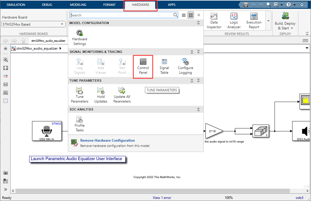
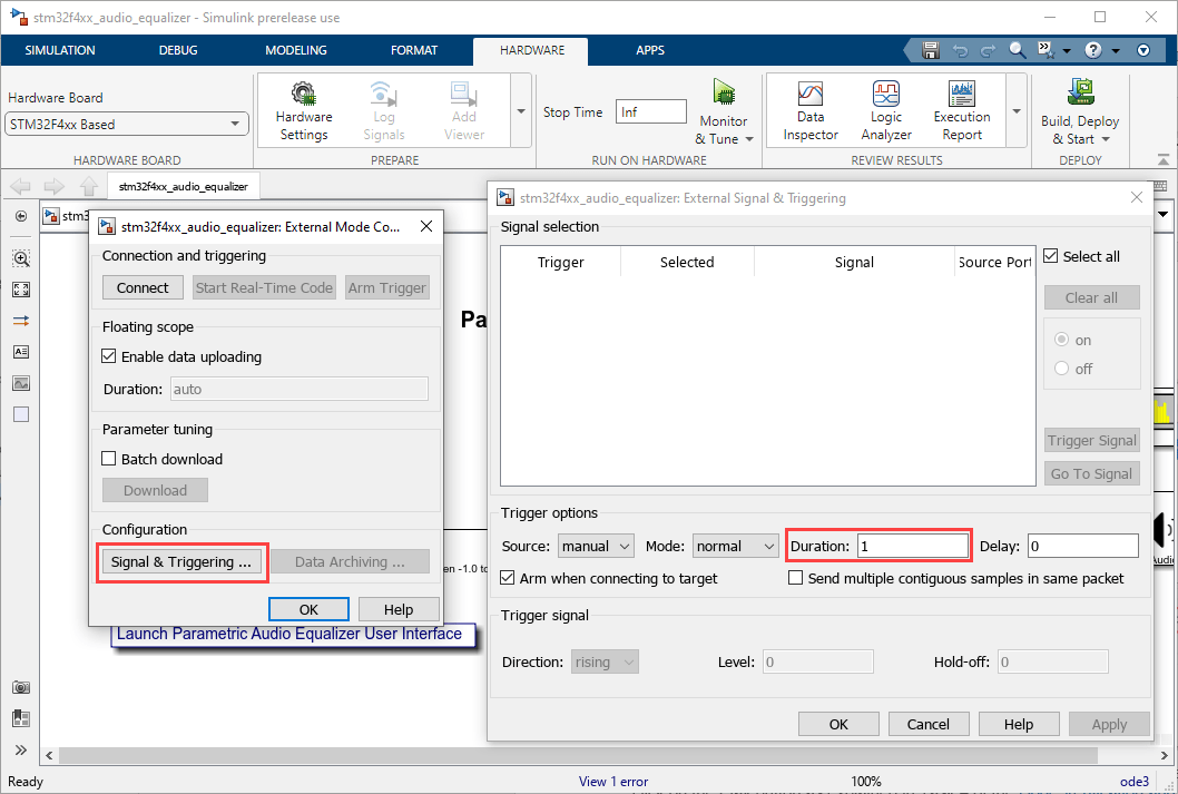
3. Click Signal & Triggering on the Connection and triggering dialog box.
4. Select the signal from Signal selection dialog box and set the Duration to '1'.
To start the Monitor and Tune simulation, switch the model simulation mode to Monitor and Tune and click on the Play button as explained in the Monitoring and Tuning Using STMicroelectronics STM32 Processor Based Boards example.
External mode verbose mode is enabled by default in this example, which enables the display of debug messages for each Monitor and Tune operation. Once the simulation starts, double click on the Parametric Audio Equalizer block to launch the User Interface to tune the filter coefficients from the GUI. You can change center frequencies, bandwidths and gains for the three equalizer bands from the GUI.
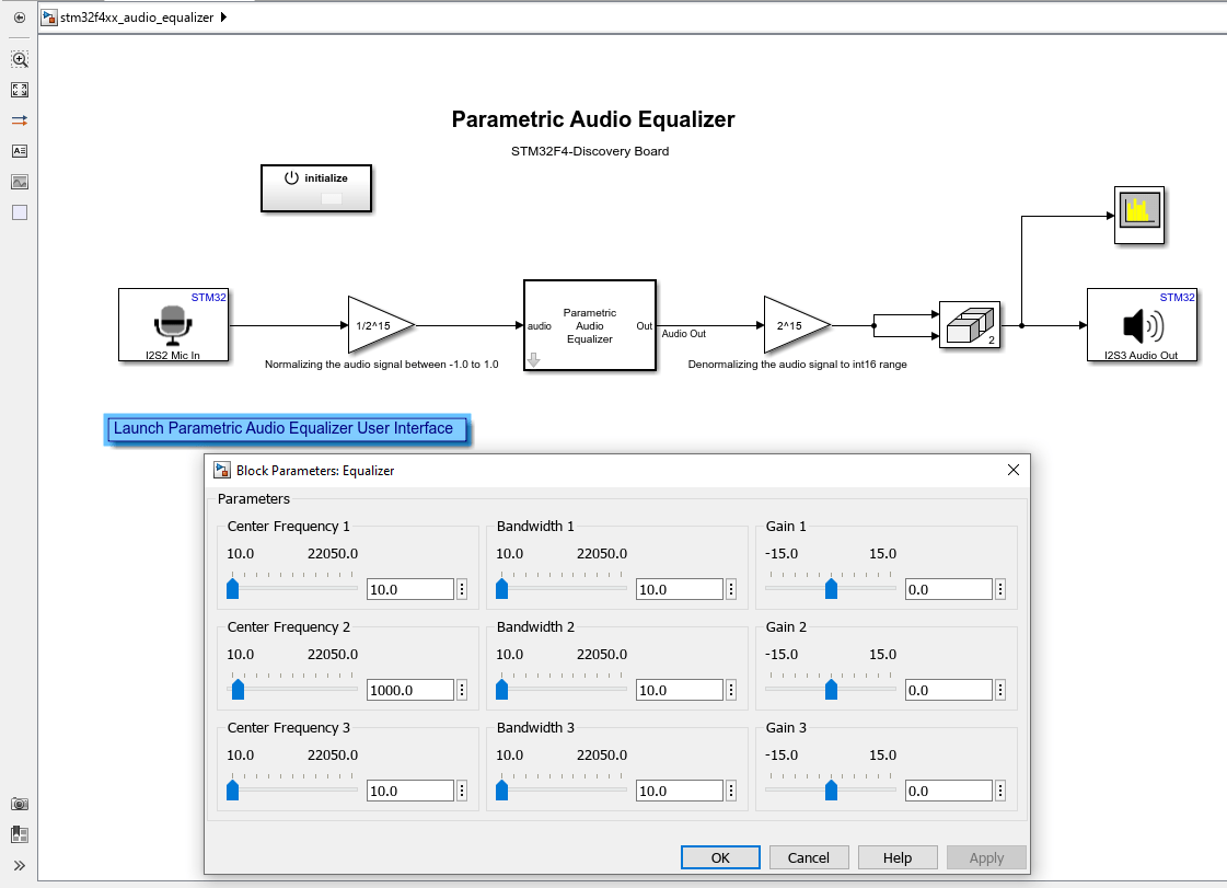
New coefficients generated by the GUI will be sent to the target. The verbose mode message "Got EXT_SETPARAM_RESPONSE from target with status OK" on the MATLAB® command window will indicate a successful update of filter coefficients. You can watch the response of the audio equalizer algorithm running on the target using the Spectrum Analyzer. External mode allows data to be updated from the target to the Spectrum Analyzer GUI.
Summary
This example showed how to generate code taking advantage of Code Replacement Library (CRL) for ARM Cortex-M CMSIS DSP functions, using the audio blocks available for the STM32 Discovery board. Performing Monitor and Tune on the audio algorithm showed how to tune parameters and watch live data running on the target.