MAT-file Logging on SD Card for STMicroelectronics STM32 Processors
This example shows you how to perform MAT-file logging using Simulink® model on a Micro SD card mounted on an STMicroelectronics® STM32 processor based board.
Introduction
The support package for STM32 boards supports logging of signals from Simulink models. These signals are logged as MAT-file(s) on a Micro SD card mounted on an STM32 processor board.
Signal logging enables you to monitor the signal behavior and to perform any historical analysis of the data. The data can be saved in any of these formats: Structure, Structure with time, or Array. You can save the signals using the following blocks:
To Workspace
Scope
Output port
This example provides you with the workflow to enable MAT-file logging and obtain the MAT-file on a Micro SD card mounted on an STM32 processor board.
You can use Embedded Coder® Support Package for STMicroelectronics® STM32 Processors to log data from Simulink blocks to an SD card mounted on STM32F2xx, STM32F4xx, STM32F7xx, STM32H7xx, and STM32L4xx based boards.
Required Hardware
To run this example, you need the following hardware:
STMicroelectronics STM32 board
External SD card interface(optional)
Micro SD card
Hardware Connection (For External SD Card Interface)
For external SD card interface, based on SD protocol, the CMD, CLK, D0-3,Vcc, GND,CD pins are to be connected to corresponding pins of STM32 board.
Connect VCC and GND pins to appropriate supply and ground.
Prepare the Connection and Configure a Simulink Model for MAT-File Logging
The MAT-file logging needs to be configured on the Simulink model so that the selected signals are logged on the Micro SD card on the STM32 processor board.
Insert the Micro SD card in the slot provided on the board.
Open the
stm32xxxx_matfile_loggingmodel. This Simulink model is pre-configured with MAT-File logging enabled. In this example, signals from the Scope block are logged.

Configure Model to Enable MAT-File Logging
To save signals on an SD card, the target hardware details must be specified.
In your model window, open the Configuration Parameters dialog box, go to the Hardware Implementation pane, and select the name of the target hardware from the Hardware board list.
In the Hardware board settings pane, expand Target hardware resources and select SD card logging.
Select Enable MAT-file logging on SD card option.
From the Interface list, select the desired interface. The default values vary based on the Hardware board selected.
To verify the status of logging through GPIO, select the Enable logging status on GPIO. Select the GPIO group and pin values from the drop down.
Click Apply. Click OK to save your changes.

Configure IOC to Enable SD Card Logging
To save signals on an SD card, following need to be configured in IOC.
Configure SD Card Interface
Select the
Modeas SD x bit xxxx for the interface mentioned in the model configuration settings.Provide a clock divide factor such that the clock to the peripheral is 187kHz and 24MHz. Also sometimes the sd card logging may not work for smaller values of divide factor. So in that scenario, increase the clock divide factor. A clock factor of 10 can be taken as rough value to start with.

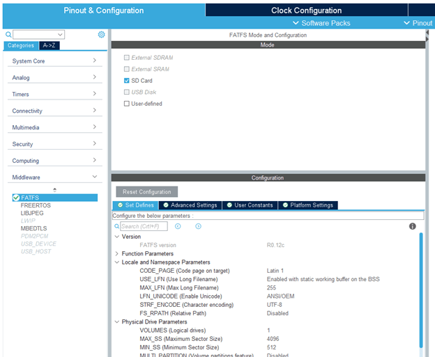
Configure FATFS
Select the
Modeas SD Card for FATFS option in Middleware.Enable the Use Long Filename so that there is no restriction on characters in file name.
Select a GPIO which is connected to SD detect pin on the sd card daughter board as GPIO Input.
Enable GPIO Logging Status Output
Select GPIO for enabling the logging status as GPIO output. A user LED is recommended for visual cue about the logging status.
Configure Scope Block for Logging
Double-click the Scope block in the Simulink model. In the Scope dialog box, click the gear icon (Configuration Properties).
In the Configuration Properties: Scope dialog box, open the Logging tab, and select Log data to Workspace. Also select Limit data points to last and set a value of
512.Select the Save format as
Array/Structure with Time/Structureand click Apply and then OK.

Configure Model Stop Time
On the Modeling tab, enter a value for the stop time. This is the duration for which the signal is logged. However, the model continues to run on the hardware and it is not affected by the time specified.
For example, in the stm32xxxx_matfile_logging model, the stop time is 10. The signal will be logged for 10 seconds. If the stop time is Inf, the signal will be logged till the Micro SD card is full or the board is disconnected.
Deploy the Model on STM32 Discover Board and View the MAT-files
After the Simulink model is configured for MAT-file logging, you can deploy the model on the connected STM32 processor board and view the MAT-file(s) created on the Micro SD card.
In the Simulink model, go to Hardware tab and click Build, Deploy & Start button. The build process for the model starts and it is deployed on the STM32 processor board. On successful deployment of the model, the LED on the board starts blinking.
To view the logged MAT-files, remove the Micro SD card from the board after the simulation time, and insert the card on your computer.
If the deployment of the model was successful, at least two MAT-files are generated on the Micro SD card.
After importing the MAT-files to your computer, you can use it for further analysis in MATLAB®.
Because the model running on the hardware creates multiple MAT-files, the logged data points are distributed across the generated MAT-files. You can create a stitcher function to combine these MAT-files into a single MAT-file that contains all the logged data points. To view an example of a MAT-file stitcher and understand its usage, enter the following command in the MATLAB® command window.
edit('stm32_MAT_stitcher.m');
Note:
In some scenarios, the system may create duplicate data. Use the stm32_MAT_stitcher file to avoid this duplication.
When the stop time is relatively small (less than 5 seconds), you may observe the data loss due to hardware limitations.
Other Things to Try with MAT-file Logging on SD Card
In this example, a Scope block is used to log signals. However, the signals in a Simulink® model can also be logged on the SD card using the To Workspace block or by logging the output(s) of the Simulink® model. Explore the MAT-file logging of a Simulink model using these two techniques.