Capture PDM Stereo Audio on STM32 Processor
This example shows how to use the I2S Mic In block in a Simulink® model to acquire pulse density modulation (PDM) stereo audio data, convert it to pulse code modulation (PCM) format and visualize the audio signal using Embedded Coder® Support Package for STMicroelectronics® STM32 Processors.
Using this example, you will learn:
I2S module and PDM to PCM conversion.
Serial communication between Target and Host model.
Prerequisites
Required Hardware
FTDI connector (optional)
Hardware Connection
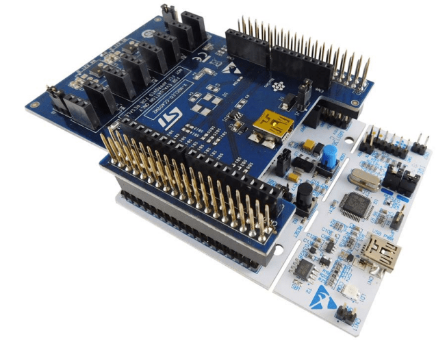
Connect the X- Nucleo-CCA02M2 shield directly on the Nucleo-F401RE board.
Available Models
I2SAudioLogger: Use the mI2SAudioLogger model to generate code and load it on the Nucleo-F401RE board.
I2SAudioVisualizer: Deploy the mI2SAudioVisualizer host model to the host computer to log signals.
Model
Open the I2SAudioLogger model.
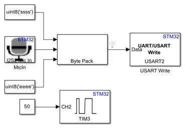
In the I2SAudioLogger target model, configure the I2S2 peripheral to stereo transmission with signal format set to 16-bits.
Clock Division for Stereo Sampling
This model uses a timer module is used to divide the I2S clock by 2. This division allows for one microphone to sample on the falling edge (left channel) while the other on the rising edge (right channel). Consequently, the I2S peripheral is able to alternately capture data from the left and right channels on the subsequent falling edges. The frequency of the clock is specifically doubled relative to the audio sampling rate to maintain this alternate sampling scheme, ensuring that both audio channels are synchronized and accurately represented in the captured audio stream.

Once the I2S peripheral acquires the audio data, it sends the data to the USART2 peripheral, which is connected to the serial port of the host via ST-LINK.
Note: Make sure to connect the USART module that you configure in the USART block to ST-LINK. If USART is not connected to ST-LINK, then use an external FTDI for USART-USB transmission.
Host Model
Open the I2SAudioVisualizer model.

The data that you transfer via USART is received by the host through the serial port to which you connect the target. Ensure the baud rate specify in the Serial Configuration block matches the rate in USART settings of the hI2SMicInPDMAudioOut_f401re.IOC file. The stereo data is divided to individual channels and you can view the resulting output in the data inspector.
Note: Ensure that the COM port of target matches the COM port of the host model. To find the COM port, browse to Device Manager > Ports (COM & LPT).
Peripheral Configurations
Set the peripheral block configurations for this model. Double-click the blocks to open block parameter configurations.
I2S Mic In block
Configure the I2S Mic In block as shown in the figure.

Model Configuration
Specify the PDM2PCM channels that you configure in CubeMX for the corresponding I2S modules in the Configuration Parameters.

STM32 CubeMX Configurations
Click Launch from Configuration Parameters to open the hI2SMicInPDMAudioOut_f401re.IOC file in the STM32CubeMX tool.
I2S CubeMX configuration
In the STM32CubeMX configure the same parameters with the same values for Frame format and frequency as that of I2S Mic In block.

Activate CRC

PDM2PCM channels
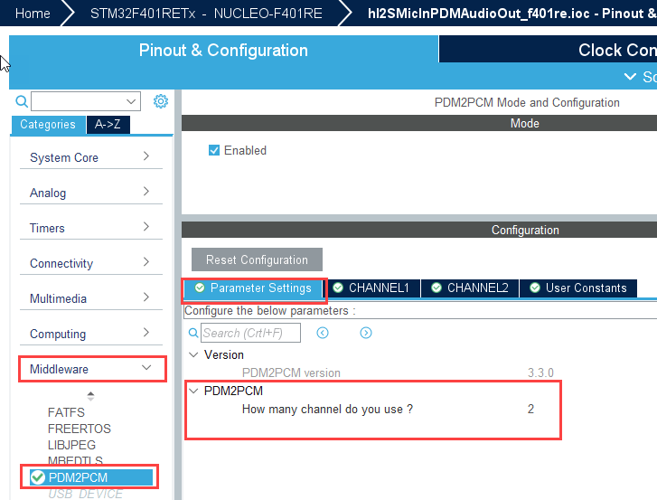
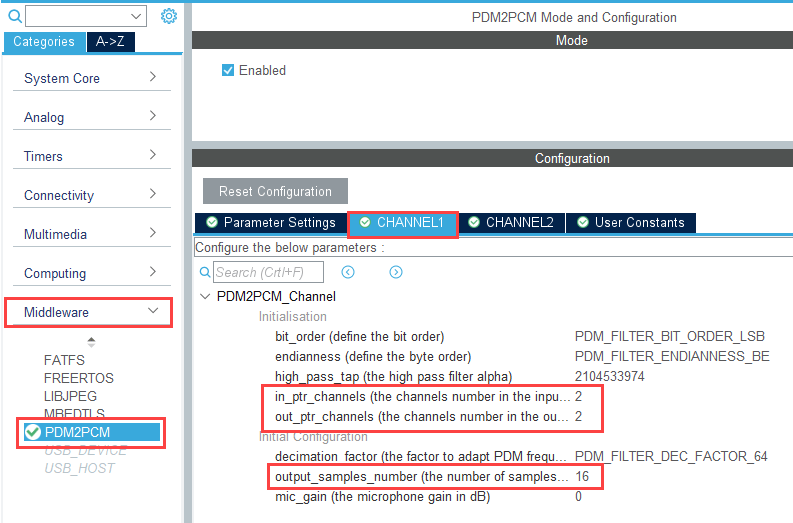
For stereo transmission, configure two PDM2PCM channels. For CHANNEL1 and CHANNEL2, set in_ptr_channels and out_ptr_channels to 2.
output_samples_number for both channels is same as the Audio frame size parameter in the I2S Mic In block.
Generate Code and Deploy on Target Hardware
This section shows you to generate code and deploy the code on the target.
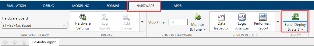
1. In the Hardware tab, click Build, Deploy & Start.
2. In the Diagnostic Viewer, observe that the code is generated for the model and the host connects to the target after loading the generated executable.
Simulate Model
This example supports simulation. Follow these steps to simulate the model.
1. Open the I2SAudioVisualizer model included with this example.
2. Click Run on the Simulation tab to simulate the model.
3. During simulation, play a sine wave of 1 kHz, which you generate using the Frequency Sound Generator mobile app. This example used the Frequency Sound Generator app from Google Play.
Other Things to Try
Configure at different rate and analyze the behavior of Sine wave.
Configure a different frequency or wave and view the results.