Using CORDIC Co-Processor Block with DMA in STMicroelectronics STM32 Processor Based Boards
This example shows how to use and generate code for a CORDIC block in a Simulink® model for STMicroelectronics® NUCLEO-G431RB board to calculate SINE and COSINE values for given values of theta by using DMA.
Prerequisites
Before running this example, complete these tutorials:
Required Hardware
The hardware required to run this example includes:
STMicroelectronics NUCLEO-G431RB board
Micro USB cable
Open Model
The GettingStartedCORDICDMA model includes a Write block, a Read block, and a Hardware Interrupt block. The Write block writes to the CORDIC write register. After the DMA Read transfer completes the interrupt, the result is read. The Hardware Interrupt is configured for the same channel. The Read block provides a valid result when the corresponding function, iteration, and array size matches.
open_system('GettingStartedCORDICDMA.slx');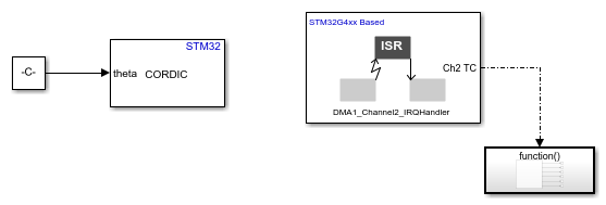
The function call subsystem in this model writes to the CORDIC peripheral.
Configure CORDIC Blocks and Hardware Interrupt Block
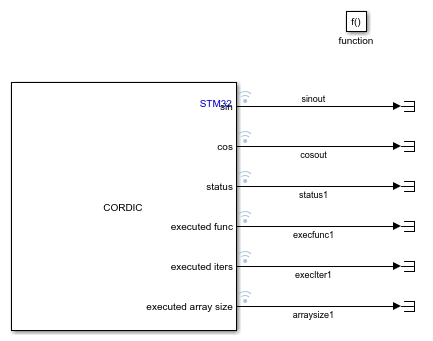
To calculate the SINE and COSINE on an array of theta on NUCLEO-G431RB board, configure the CORDIC and Hardware Interrupt blocks. The two CORDIC blocks write to the CORDIC peripheral and read the results from the peripheral separately. Results are read to the model after the completion of writing all the data points by utilizing the DMA transfer complete interrupt of the write channel.
Configure the blocks.
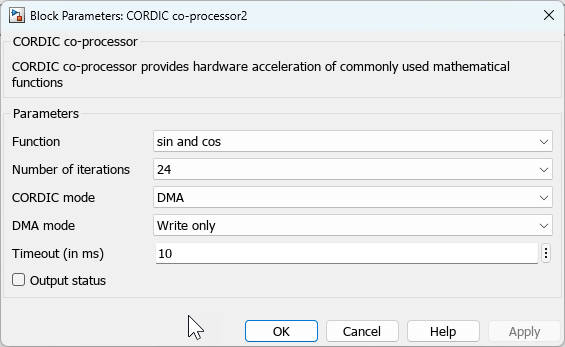
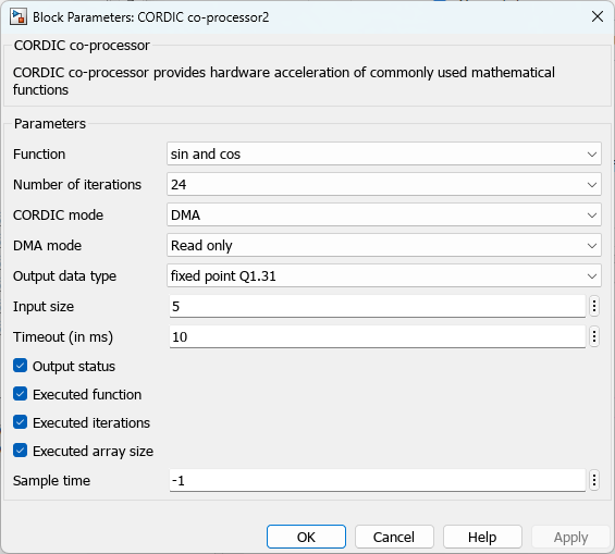
1. Double-click the respective block to open the block parameter dialog box.
2. Set the block to perform write only operation in DMA mode for each step.
Note: This configuration does not guarantee the write operation on each step as write operation is performed only after the results of previous calculation are read.
3. Set the Interrupt group and name as per the write channel of DMA for CORDIC that would be set in IOC.
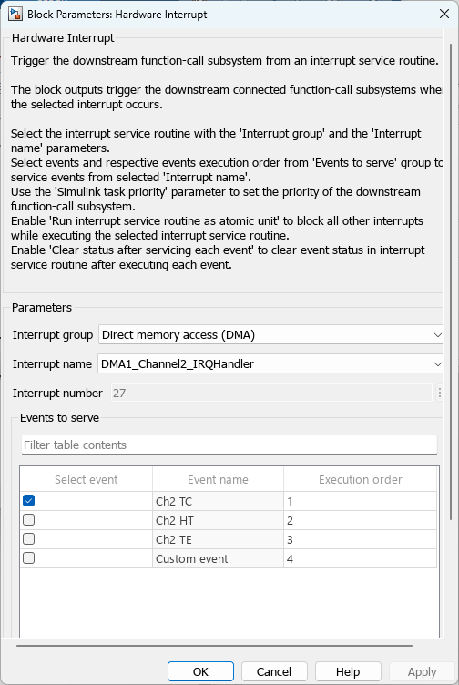
4. Set the block to perform the read operation inside the Hardware Interrupt function call subsystem. Take care that the function, iteration, and size match with the write block to which this read block corresponds. You may use the various outputs to gage the function, iteration, and size of the input that was executed in the previous step. Enable logging of the desired signals.
5. Create a new STM32CubeMX project or browse to an existing STM32CubeMX project. Launch the STM32CubeMX project in the STM32CubeMX tool. For more information, see Getting Started with STMicroelectronics STM32 Processor Based Boards.
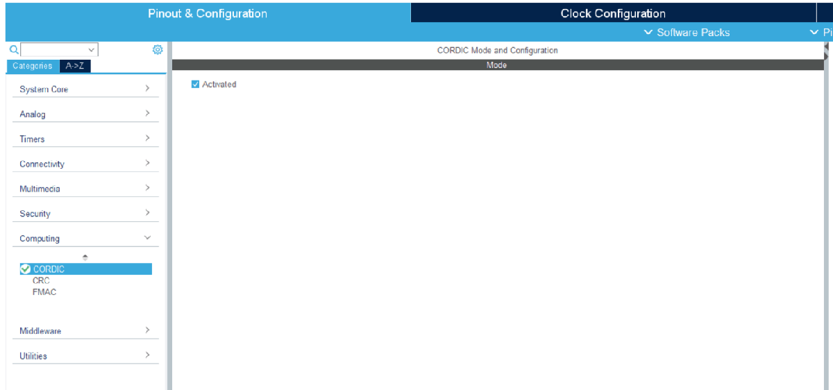
Configuration the blocks to enable the CORDIC and DMA.
1. On STM32G4xx/H723 based controllers, enable the CORDIC.
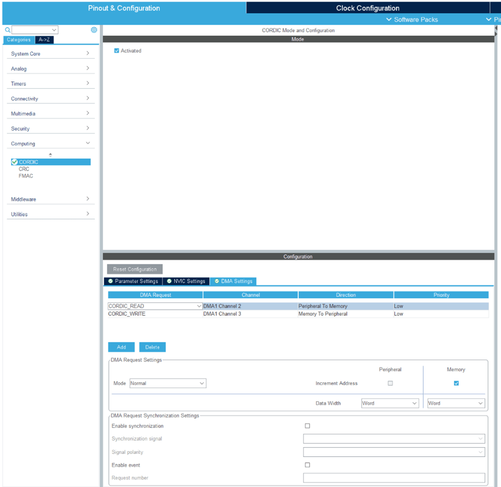
2. Enable the DMA for read and write channels and set the data width to word.
In your STM32CubeMX project, configure these settings:
Enable Do not generate the main() under Project Manager > Project.
Disable Generate under root under Project Manager > Project.
Under Project Manager > Advanced Settings > Driver Selector, select low level (LL) drivers for the peripherals.
Under Project Manager > Advanced Settings > Generate Functions Calls, deselect
Do Not Generate Function Callsfor all the peripheral initialization function calls.Under Project Manager > Advanced Settings > Generate Function Calls, deselect
Visibility (Static)for all the peripheral initialization function calls.Save the project.
Monitor and Tune the Model
When you perform Monitor & Tune action for the model, the host computer communicates with the target, on which the generated executable runs.
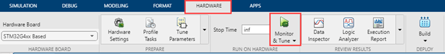
1. Open the Hardware tab and click Monitor & Tune. You can observe from the Diagnostic Viewer that the code is generated for the model and the host connects to the target after loading the generated executable.
2. While the model is running, observe the Display block to view the results.
Close Model
bdclose('GettingStartedCORDICDMA.slx');