Integrate External Application Code with Code Generated from PID Controller
This example shows how to generate C code from a control algorithm model and integrate that code with existing, external application code. In the complete application, which consists of three modules, the algorithm module must exchange data with other modules through global variables. This example inspects the external code to determine requirements in the setup of an embedded coder dictionary and establishes code mappings for a service interface configuration.
In this example you:
Inspect the model and external code to assess project requirements.
Inspect and customize default service interfaces in a coder dictionary.
Configure the model to use custom data types.
Configure the code interface to use constant parameters.
Configure the organization of the code in generated files.
Configure the model service code interfaces for code generation.
Assess model readiness for component deployment using a service interface configuration.
Generate and inspect the service interface code.
Integrate the generated service interface code with the target environment code.
Inspect Model to Assess Project Requirements
Open the example model ex_ext_ctrl_alg.
open_system('ex_ext_ctrl_alg')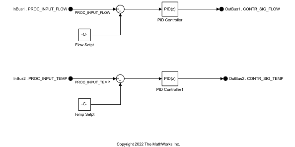
The blocks in the model implement the PID controller algorithm. The module takes the filtered sensor data and passes the signal to a Discrete-time PID Controller block with Parallel form. For each input, the module outputs the weighted sum of the input signal, the integral of the input signal, and the derivative of the input signal. The weights are the proportional, integral, and derivative gain parameters. For more information, see Discrete PID Controller.
To complete the application, you must generate code using a service interface configuration to perform the function of the ex_ext_ctrl_alg module that the model represents.
The figure below shows the intended flow of data through the three modules in the system. Notice that the three modules are all called from ext_code_main.c. The figure also shows the code files that define and declare the data (global variables) that cross the module boundaries.

Inspect External Code to Assess Project Requirements
Run the script prepare_ext_code. The script copies external code files into several folders.
exampleFolder = pwd;
run('prepare_ext_code.m');
Open ext_code_main.c. This application code represents an embedded system with a trivial scheduling algorithm (a while loop) and three modules that include algorithms that run in every execution cycle: ex_ext_inputs_proc, ex_ext_ctrl_alg, and ex_ext_outputs_proc.
type('ext_code_main.c')#include <stddef.h>
#include "ex_ext_inputs_proc.h"
#include "ex_ext_ctrl_alg.h"
#include "ex_ext_outputs_proc.h"
#include <stdio.h>
#include <string.h>
int numCycles = 0;
int main()
{
ex_ext_ctrl_alg_initialize();
do {
ex_ext_inputs_proc();
ex_ext_ctrl_alg_step();
ex_ext_outputs_proc();
numCycles = numCycles + 1;
printf("At cycle %d, out1 is %f and out2 is %f.\n", numCycles, out1, out2);
} while (numCycles <= 50);
return 0;
}
In the shared folder (exampleFolder/shared), in ex_ext_projTypes.h, notice the two custom data types (typedef) that the data in the modules use.
typedef double dataPath_flow_T;
typedef double dataPath_temp_T;
In the io_drivers folder (exampleFolder/io_drivers), in ex_sensor_accessors.c, notice the functions get_fromSensor_flow and get_fromSensor_temp, which return raw data recorded by flow and temperature sensors. For this example, the functions return trivial sinusoidal stimuli for the control algorithm.
dataPath_flow_T get_fromSensor_flow(void) {
/* Return a trivial value for this "sensor" */
return sin(numCycles);
};
dataPath_temp_T get_fromSensor_temp(void) {
/* Return a trivial value for this "sensor" */
return cos(numCycles);
};
In the ex_ext_inputs_proc folder (exampleFolder/ex_ext_inputs_proc), in ex_ext_inputs_proc.c, the ex_ext_inputs_proc module reads the sensor data (by calling the accessor functions), filters the data, and stores it in two global variables, PROC_INPUT_FLOW and PROC_INPUT_TEMP. These global variables are defined in ex_ext_proc_inputs.c and declared in ex_ext_proc_inputs.h.
dataPath_flow_T PROC_INPUT_FLOW;
dataPath_temp_T PROC_INPUT_TEMP;
The filter algorithm in this module and the algorithms in the other two modules require state data, which must persist between execution cycles of the application. Each module stores relevant state data as global variables. For example, in the ex_ext_inputs_proc module, ex_ext_inputs_proc.c defines these variables:
flowFilterIn_state_datatempFilterIn_state_dataflowFilterIn_tmp_datatempFilterIn_tmp_data
The empty ex_ext_ctrl_alg folder is a placeholder for the generated code. The ex_ext_ctrl_alg module must perform PID control on the filtered flow and temperature measurements.
In the ex_ext_outputs_proc folder (exampleFolder/ex_ext_outputs_proc), in the file ex_ext_outputs_proc.c, the ex_ext_outputs_proc module reads the PID output signals from global variables named CONTR_SIG_FLOW and CONTR_SIG_TEMP. The ex_ext_ctrl_alg module (the generated code) must define these variables. The ex_ext_ctrl_alg module filters these signals and passes the filtered values to functions that represent device drivers for actuators (for example, a valve and a heater filament).
/* Filter algorithm for flow control. */
flowFilterOut_tmp_data = (CONTR_SIG_FLOW - 1.92 *
flowFilterOut_state_data) / 1.78;
/* Write filtered control output to flow valve. */
set_toActuator_flow(2.15 * flowFilterOut_tmp_data);
/* Filter algorithm for temperature. */
tempFilterOut_tmp_data = (CONTR_SIG_TEMP - 1.95 *
tempFilterOut_state_data) / 2.11;
/* Write filtered control output to heater filament. */
set_toActuator_temp(1.65 * tempFilterOut_tmp_data);
The actuator functions are defined in the io_drivers folder in the file ex_actuator_accessors_c.
To perform the function of the control algorithm module and integrate with the external code, the generated code must:
Use the custom data types
dataPath_flow_TanddataPath_temp_Tdeclared in the external fileex_ext_projTypes.h.Read filtered sensor data from global variables
PROC_INPUT_FLOWandPROC_INPUT_TEMP. The generated code must not define these variables because the moduleex_ext_inputs_procdefines them, declaring them in ex_ext_proc_inputs.h.Write PID control signals to global variables named
CONTR_SIG_FLOWandCONTR_SIG_TEMP. The generated code must define these variables and declare them in fileex_ext_ctrl_sigs.h. Then, theex_ext_outputs_procmodule can read the raw control signals from them.Conform to variable naming standards that govern the external application. For example, the generated code must store state data in global variables with names that end in
_data. In addition, the names of local variables must end in_local.Conform to standards that govern the organization of the code in each of the external files. For example, each file contains sections, delimited by comments, which aggregate similar code constructs such as type definitions, variable declarations, and function definitions.
Define and declare const global variables named
PARAM_setpoint_flowandPARAM_setpoint_temp, which represent the PID controller setpoints. The definitions must be in a file namedex_ext_ctrl_params.cand the declarations must be in a file namedex_ext_ctrl_params.h.
Inspect and Customize Default Service Interfaces in a Coder Dictionary
You address the external code requirements by defining a service code interface configuration in a shared Embedded Coder Dictionary. This example generates code from a component model that uses a C service code interface configuration. Model data elements are mapped to service interfaces defined in the Embedded Coder Dictionary. This example shows how to customize the default service interfaces and define new service interfaces in a dictionary.
For more information, see C Service Interfaces and Embedded Coder Dictionary.
Create a Shared Embedded Coder Dictionary
In the Embedded Coder App, select C Code > Code Interface >
Set up shared Embedded Coder Dictionary.Select
Create Embedded Coder Dictionaryand name the dictionary “PIDControllerDictionary.sldd”.Select
Service Interfaceas the code interface type and click Create.
For this example, to meet the code interface requirements listed in Inspect Model to Assess Project Requirements and Inspect External Code to Assess Project Requirements, make these adjustments:
Under Execution, in Initialize and Terminate, change Function Naming Rule for
InitTermto$R_initialize.Under Execution, in Periodic and Aperiodic, change Function Naming Rule for
PeriodicAperiodicExample1to$R_step. Change Name toPeriodicAperiodic.Under Memory, in Storage Class, create a new storage class with Name set to
ImportFromFile, Data Scope set toImported, and Header File set toex_ext_proc_inputs.h.Create a second storage class with Name set to
ExportToFile, Data Scope set toExported, Header File set to$R_sigs.h, and Definition File set to$R_sigs.c.Create a third storage class with Name set to
Const, Data Scope set toExported, Header File set to$R_params.h, Definition File set to$R_params.c, Data Initialization set toConst. Under Qualifiers, selectconst.Under Service Interfaces, in Data Receiver, change the Storage Class of
ReceiverExample3toImportFromFile. In the middle table, select this service interface as Dictionary Default. Change Name toReceiverDirect.Under Service Interfaces, in Data Sender, change the Storage Class of
SenderExample3toExportToFile. Select this service interface as Dictionary Default. Change Name toSenderDirect.Under Service Interfaces, in Parameter Tuning, create a new service interface with Name set to
PARAM_setpoint_flowand Storage Class set toConst. Create a second new service interface with Name set toPARAM_setpoint_tempand Storage Class set toConst.
Consider removing service interface entries that are not used by selecting the trash can icon next to each unused service interface listed in the middle column of the dictionary.
For more information, see Code Interface Definitions.
Configure Model to Use Custom Data Types
Set your current folder to the shared folder.
Use the function Simulink.importExternalCTypes to generate Simulink.AliasType objects that represent the custom data types dataPath_flow_T and dataPath_temp_T.
cd('shared');
Simulink.importExternalCTypes('ex_ext_projTypes.h');
The objects appear in the base workspace.
Open the Model Data Editor by using the tab near the bottom the app window.
In the Model Data Editor, for the Inport block that represents
PROC_INPUT_FLOW, set Data Type todataPath_flow_T. To add the custom data types to the Data Type list, clickRefresh data types.For the Inport block that represents
PROC_INPUT_TEMP, set Data Type todataPath_temp_T.Select the Signals tab.
Configure the data type for the Constant blocks. For each Constant block, in the model, select the block output signal. Then, in the Model Data Editor, set Data Type to
Inherit: Inherit via back propagation. With this setting, the Constant blocks inherit the output data type of the block immediately downstream. In this case, the downstream block is a Sum block.
Update the block diagram. The diagram shows that, due to data type inheritance and propagation, signals in the model use a custom data type.
Configure Code Interface to Use Constant Parameters
To apply a storage class to the parameters represented by Constant blocks Flow Setpt and Temp Setpt, use the Model Explorer to create Simulink.Parameter objects to represent the data. Create two model workspace parameters.
Open the Model Explorer.
In the Model Hierarchy pane, select Model Workspace.
Create two parameter data objects. Select Add > Simulink Parameter. Name the parameter objects
PARAM_setpoint_flowandPARAM_setpoint_temp. Set the value ofPARAM_setpoint_flowto3. Set the value ofPARAM_setpoint_tempto2.To configure the storage class for the model parameters, click Configure.
In the Embedded Coder app, in the Code Mappings editor, click the Data Defaults tab.
Expand Parameters.
For Model Parameters, set Storage class to
Const. Click the pencil icon and set the HeaderFile property toex_ext_ctrl_params.hand the DefinitionFile property toex_ext_ctrl_params.c.On the Parameters tab, for each parameter, set Storage Class to
Model default: Const.In the model, for Constant block
Flow Setpt, set block parameter Constant value toPARAM_setpoint_flow. For Constant blockTemp Setpt, set Constant value toPARAM_setpoint_temp.For the parameters to be tunable, set model configuration parameter Default parameter behavior to
Tunable.Save the model.
Configure Naming Rules for Variables
In the external code, internal data that does not participate in the module interfaces, such as state data and local variables in functions, conform to naming schemes. In the model, configure internal data that appears in the generated code to align with the external code naming schemes.
1. In the model Configuration Parameters dialog box, open the Code Generation > Identifiers pane.
2. Set Global variables to naming rule $R$N_data$M. This setting controls the names of global variables, such as those that represent state data. The naming rule $R$N_data_$M most closely approximates the scheme that the state variables in the external code use. In the naming rule:
$Rrepresents the name of the model,ex_ext_ctrl_alg.$Nrepresents the name of the model element to which the naming rule applies, such as a signal, block state, or standard data structure.$Mrepresents name-mangling text that the code generator inserts to avoid name clashes. For most naming rules, this token is required.
3. Set Local temporary variables and Local block output variables to $N_local$M.
Configure Organization of Code in Generated Files
To match the organization of the files in the example external code, use the example template file ex_my_code_template.cgt. The template governs the organization and appearance of code in each generated file. For example, the template organizes similar code constructs into named sections (delimited by comments) and, at the top of the template, specifies minimal information about each generated file.
1. Copy ex_my_code_template.cgt to the ex_ext_ctrl_alg folder.
cd(exampleFolder);
copyfile("ex_my_code_template.cgt","ex_ext_ctrl_alg");
2. In the model Configuration Parameters dialog box, open the Code Generation > Templates pane.
3. Under Code templates and Data templates, set parameters Sourc file template and Header file template to ex_my_code_template.cgt.
Configure Model Service Code Interfaces for Code Generation
You determine whether to deploy your top model as an application or component based on the requirements for your project. In this example, the external code defines the requirements for the generated code in order to successfully integrate. Component deployment requires integration of generated function code with an external function scheduler and other target environment software. For this example, deploy the model as a component. For more information, see Deploy Generated Software.
For the code generator to produce interface code that aligns with the target environment requirements, there needs to be a mapping between the interface elements in the model and code interfaces. For this example, the code generator applies a service interface because the model is attached to shared Embedded Coder Dictionary PIDControllerDictionary.sldd, which defines a service interface configuration. The code generator uses the attached dictionary to establish default mappings that you can view and change by using the Code Mappings Editor or code mappings programming interface.
To open the Code Mappings editor and explore the interface settings, in the Embedded Coder app, under Code Interface, select Component Interface.
For this example, to meet the code interface requirements listed in Inspect Model to Assess Project Requirements and Inspect External Code to Assess Project Requirements, make these adjustments:
On the Functions tab, set the Function Customization Template for
InitializetoDictionary default: InitTerm. Then, set the Function Customization Template forPeriodic:D1 [Sample Time: 0.2s]toDictionary default: PeriodicAperiodic.On the Inports tab, set the Receiver Service for
PROC_INPUT_FLOWandPROC_INPUT_TEMPtoDictionary default: ReceiverDirect.On the Outports tab, set the Sender Service for
CONTR_SIG_FLOWandCONTR_SIG_TEMPtoDictionary default: SenderDirect.On the Parameters tab, set the Parameter Tuning Service for
PARAM_setpoint_flowtoPARAM_setpoint_flow. Then, set the Parameter Tuning Service forPARAM_setpoint_temptoPARAM_setpoint_temp.
For more information, see Code Mappings Editor — C.
Assess Model Readiness for Component Deployment Using a Service Interface Configuration
Run the Simulink Model Advisor to confirm that the component model passes component modeling guideline and service interface configuration checks.
In the Embedded Coder app, select C/C++ Code Advisor.
In the System Selector dialog box, select
ex_ext_ctrl_alg. Click Ok.In the Code Generation Advisor dialog box, in the left pane, select Model Advisor.
In the Model Advisor dialog box, in the left pane, expand
By ProductandEmbedded Coder.Select the checks Check modeling style for component deployment, Check signal interfaces, and Check configuration for component deployment.
Run the selected checks.
If the checks do not pass, use the information provided to correct the conditions reported.
For more information, see Modeling Guidelines for Generated Code and Model Readiness for Code Generation.
Generate and Inspect Service Interface Code
Because the external code defines a main function, select model configuration parameter Generate code only and clear parameter Generate an example main program.
set_param('ex_ext_ctrl_alg','GenCodeOnly','on');
set_param('ex_ext_ctrl_alg','GenerateSampleERTMain','off');
Generate code from the model.
slbuild('ex_ext_ctrl_alg');### Searching for referenced models in model 'ex_ext_ctrl_alg'. ### Total of 1 models to build. ### Starting build procedure for: ex_ext_ctrl_alg ### Successful completion of code generation for: ex_ext_ctrl_alg Build Summary Top model targets: Model Build Reason Status Build Duration ===================================================================================================== ex_ext_ctrl_alg Information cache folder or artifacts were missing. Code generated. 0h 0m 14.48s 1 of 1 models built (0 models already up to date) Build duration: 0h 0m 15.506s
Use the Code Interface Report to inspect and verify that the generated code follows requirements. The Code Interface Report documents the generated code interface including model entry-point functions and services. The code interface information helps you to review the generated code and integrate it with other code.
In the Code Generation Report, in the left side panel, select Code Interface Report.
Under Initialize Functions, notice that
ex_ext_ctrl_alg_initializefollows the naming scheme for the initialization function required by the external code.Under Periodic Functions, notice that
ex_ext_ctrl_alg_stepfollows the naming scheme for the step function required by the external code.Under Parameter Tuning Service Interfaces, notice that
PARAM_setpoint_flowhas data typedataPath_flow_TandPARAM_setpoint_temphas data typedataPath_temp_T. Also notice that both parameters follow the naming scheme required by the external code and are constant variables.
For more information, see Analyze Generated Service Code Interface Report.
Integrate Generated Service Interface Code with Target Environment Code
Generated code will be placed into the folder ex_ext_ctrl_alg_ert_rtw.
To integrate the generated component code with a main function and other target environment code, you must:
Match the service interfaces of the generated code with other interfaces of existing external code.
Connect input and output data.
Access other data, such as constant global variables in this example.
In this example, make these adjustments to connect input and output data:
Import input data from the external code to the generated code. Notice that external code file
ex_ext_proc_inputs.his included (#include) in the generated code fileex_ext_ctl_alg.c.Export output data from the generated code to external code. Include (
#include) header fileex_ext_ctrl_alg_sigs.hin the external code fileex_ext_outputs_proc.h.
Function and variable names in the external code match with function and variable names in the generated code as a result of the naming rules defined in the coder dictionary.
Create an instance of the code descriptor object to get additional information about the service interface and use the results to confirm that generated interfaces meet integration requirements.
codeDescObj = coder.getCodeDescriptor('ex_ext_ctrl_alg');
serviceObj = codeDescObj.getServices();
For example, to retrieve the name of the header file that contains the service interface prototypes, use the getServicesHeaderFileName method. The code generator returns a character vector that represents the header file name.
serviceHeaderFile = getServicesHeaderFileName(serviceObj)
serviceHeaderFile =
'services.h'
For more information about commands to retrieve metadata about service interfaces, see Get Metadata About Service Interface.
See Also
Topics
- Choose an External Code Integration Workflow
- Exchange Data Between External C/C++ Code and Simulink Model or Generated Code
- Control Data and Function Interface in Generated Code
- Configure Generated Code According to Interface Control Document Specifications
- How Generated Code Stores Internal Signal, State, and Parameter Data