Document Generated Code with Simulink Report Generator
The Simulink® Report Generator™ software creates documentation from your model in multiple formats, including HTML, PDF, RTF, Microsoft Word, and XML. This example shows one way to document a code generation project in Microsoft® Word. The generated report includes:
System snapshots (model and subsystem diagrams)
Block execution order list
Simulink Coder™ and model version information for generated code
List of generated files
Optimization configuration parameter settings
System target file selection and build process configuration parameter settings
Subsystem map
File name, path, and generated code listings for the source code
To adjust Simulink Report Generator settings to include custom code and then generate a report for a model, complete the following tasks:
A Simulink Report Generator license is required for the following report formats: PDF, RTF, Microsoft Word, and XML. For more information on generating reports in these formats, see the Simulink Report Generator documentation.
Generate Code for the Model
Before you use the Report Generator to document your project, generate code for the model.
In the MATLAB® Files panel, navigate to a folder where you have write access.
Create a working folder from the MATLAB command line by typing:
mkdir report_exMake
report_exyour working folder:cd report_exOpen the
slexAircraftExamplemodel. In the Command Window, enter:openExample('slexAircraftExample')On the Simulation tab, in the Save list, select Save as. Navigate to the working folder,
report_ex, and save a copy of theslexAircraftExamplemodel asmyModel.Open the Configuration Parameters dialog box. Set the Solver > Solver selection > Type parameter to
Fixed-step.Select the Code Generation pane. Select Generate code only.
Click Apply.
In the model window, press Ctrl+B. The build process generates code for the model.
Open the Report Generator
After you generate the code, open the Report Generator.
Open the Report Generator app. In the model diagram window, in the Apps gallery, click Report Generator.
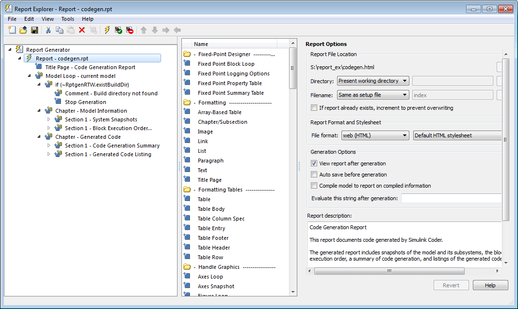
In the Report Explorer window, in the options pane (center), click the folder rtw (\toolbox\rtw). Click the setup file that it contains, codegen.rpt.

Double-click codegen.rpt or select it and click the Open report button. The Report Explorer displays the structure of the setup file in the outline pane (left).

Set Report Name, Location, and Format
Before generating a report, you can specify report output options, such as the folder,
file name, and format. For example, to generate a Microsoft Word report named MyCGModelReport.rtf:
In the properties pane, under Report Options, review the options listed.

Leave the Directory field set to
Present working directory.For Filename, select
Custom:and replaceindexwith the nameMyModelCGReport.For File format, specify
Rich Text
                        Format
and replaceStandard PrintwithNumbered Chapters & Sections.
Include Models and Subsystems in a Report
Specify the models and subsystems that you want to include in the generated report by setting options in the Model Loop component.
In the outline pane (left), select Model Loop. Report Generator displays Model Loop component options in the properties pane.
If not already selected, select
Current block
                        diagram
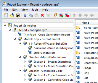
for the Model name option.In the outline pane, click Report - codegen.rpt*.

Customize the Report
After specifying the models and subsystems to include in the report, you can customize the sections included in the report.
In the outline pane (left), expand the node Chapter - Generated Code. By default, the report includes two sections, each containing one of two report components.
Expand the node Section 1 — Code Generation Summary.
Select Code Generation Summary. Options for the component are displayed in the properties pane.
Click Help to review the report customizations that you can make with the Code Generation Summary component. For this example, do not customize the component.
In the Report Explorer window, expand the node Section 1 — Generated Code Listing.
Select Import Generated Code. Options for the component are displayed in the properties pane.
Click Help to review the report customizations that you can make with the Import Generated Code component.
Generate the Report
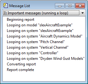
After you adjust the report options, from the Report Explorer window, generate the report by clicking File > Report. A Message List dialog box opens, which displays messages that you can monitor as the report is generated. Model snapshots also appear during report generation. The Message List dialog box might be hidden behind other dialog boxes.

When the report is complete, open the report,
MyModelCGReport.rtf in the folder report_ex
(in this example).