Read and Write Data over Serial Port on NVIDIA Jetson Platforms
This example shows how to use MATLAB® Coder™ Support Package for NVIDIA® Jetson® and NVIDIA DRIVE® to read and write serial data over the UART port on a Jetson board.
Using this example, you can create and deploy a Simulink® model that can:
Receive data from the host computer through serial communication.
Send data to the host computer through serial communication.
Prerequisites
NVIDIA Jetson Nano embedded platform.
Ethernet crossover cable to connect the target board and host PC (if you cannot connect the target board to a local network).
USB to serial converter.
Tools, libraries, and environment variables on the target board for the compilers and libraries. For more information, see Prerequisites for Generating Code for NVIDIA Boards.
Setup Jetson for Serial Communication
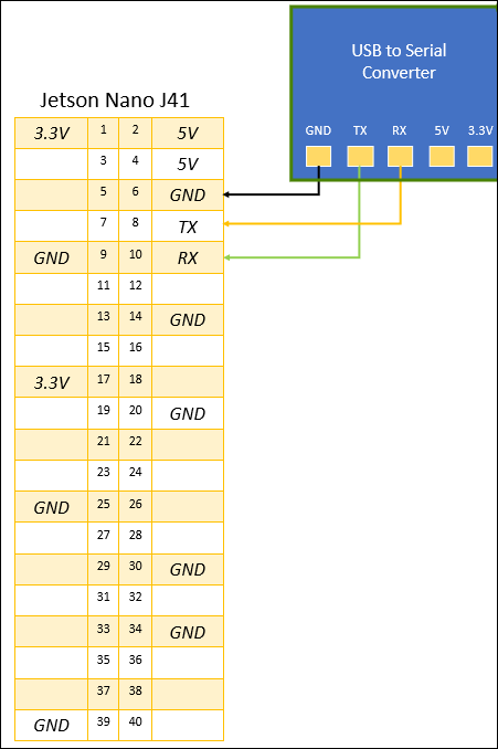
Connect the Tx and Rx pins of the USB to serial converter to the Rx and Tx pins on the Jetson board.
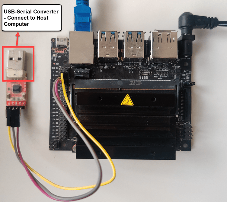
Connect the USB to serial converter to the host computer.
Simulink Model for Serial Communication
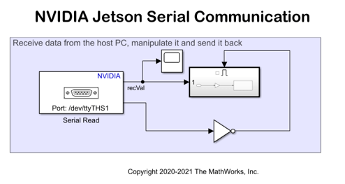
This example uses a preconfigured jetsoncpu_serial_communication model that uses the Serial Read and Serial Write blocks to exchange the data over the UART port on a Jetson board. In this model, the Jetson board receives the serial data from the host computer using a USB to serial converter, manipulates the data, and sends it back to the host computer.
mdlName = "jetsoncpu_serial_communication";
open_system(mdlName);
Configure Board Parameters of the Model
To set up a live connection to the Jetson board, specify the device address, username, and password of the Jetson Nano board.
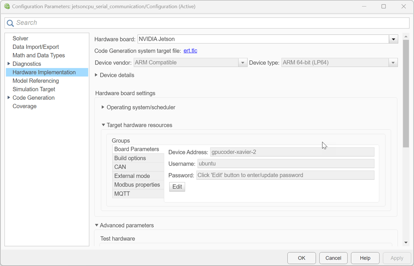
Open the Configuration Parameters dialog box and navigate to the Hardware Implementation pane.
Select your target hardware from the Hardware board drop-down list.
Set the Hardware board to NVIDIA Jetson
In the Target Hardware Resources section, open the Board Parameters pane and enter the device address, username, and password for the Jetson board.
Click Apply and then OK to close the dialog box.
Configure Serial Blocks
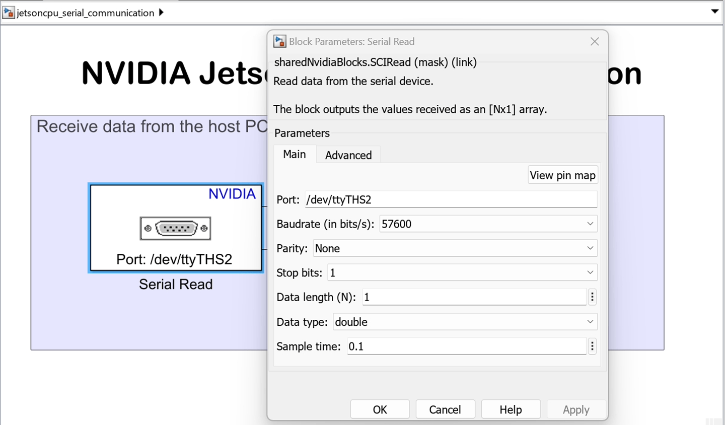
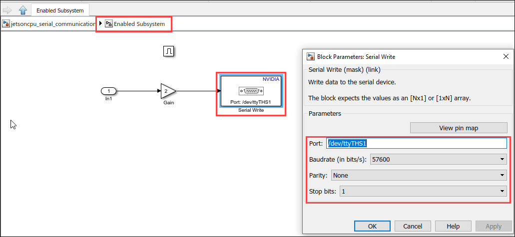
In the Simulink model, double-click the following blocks and verify that the specified parameter values are the same as shown below:
Serial Read block in the Jetson Serial Communication model
Serial Write block in the Enabled subsystem
Configure Host Script
The example uses the jetsoncpu_serial script to enable the host computer send data to the Jetson board,read the data coming from the board via serial port, and display the serial data.
type jetsoncpu_serial.m
function jetsoncpu_serial()
%   Copyright 2021 The MathWorks, Inc.

% Enter the COMPort of the USB-Serial converter connected to the host.
comPort = 'COM3';

% Enter the Baud rate at which the data is sent and received. Make sure
% this is the same value as the one used by the Jetson board.
baudRate = 57600;

% Create a serial object to start the communication
serObj = serialport(comPort, baudRate);

% sendVal is the number to be sent to the target.
sendVal = pi;
disp(['Send number: ' num2str(sendVal)]);
write(serObj, sendVal, 'double');

% recVal is the number received from the target.
recVal = read(serObj, 1, 'double');
disp(['Received number: ' num2str(recVal)]);

end
In the script, specify the comPort associated with the USB to serial converter.
To find the COM port associated with the USB to serial converter on a Windows® machine,
Open Device Manager in Windows.
Expand the Ports tab (Device Manager > Ports (COM & LTP) in Windows).
Note the COM port associated with the USB to Serial Converter.
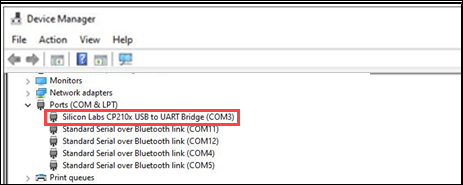
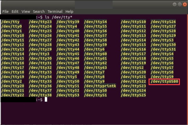
To find the COM port associated with the USB to serial converter on a Linux® machine,
Open a terminal.
Type
ls /dev/tty*in the terminal and press enter.Note the COM port associated with the USB to serial converter.
Monitor and Tune Model
When you monitor and tune the Jetson Serial Communication model, the host computer communicates with the target on which the generated executable runs.
To monitor and tune the model, open the Hardware tab and click Monitor & Tune. You can observe from the Diagnostic Viewer that the code is generated for the model and the host connects to the target after loading the generated executable.

Run the jetsoncpu_serial.m script.
The script sends the Pi value to the Jetson board.
The Jetson board multiplies it with the Gain block value specified in the model and sends it to the host.
The script receives this value and displays it in the Command Window.

Change the value in the Gain block and rerun the script. Observe the new values in the command window.
To stop external simulation, go to the Hardware tab and click the Stop button to terminate external mode simulation.

Other Things to Try
Replace the Gain block with other computation blocks.