HDL Minimum Phase FIRT Filter
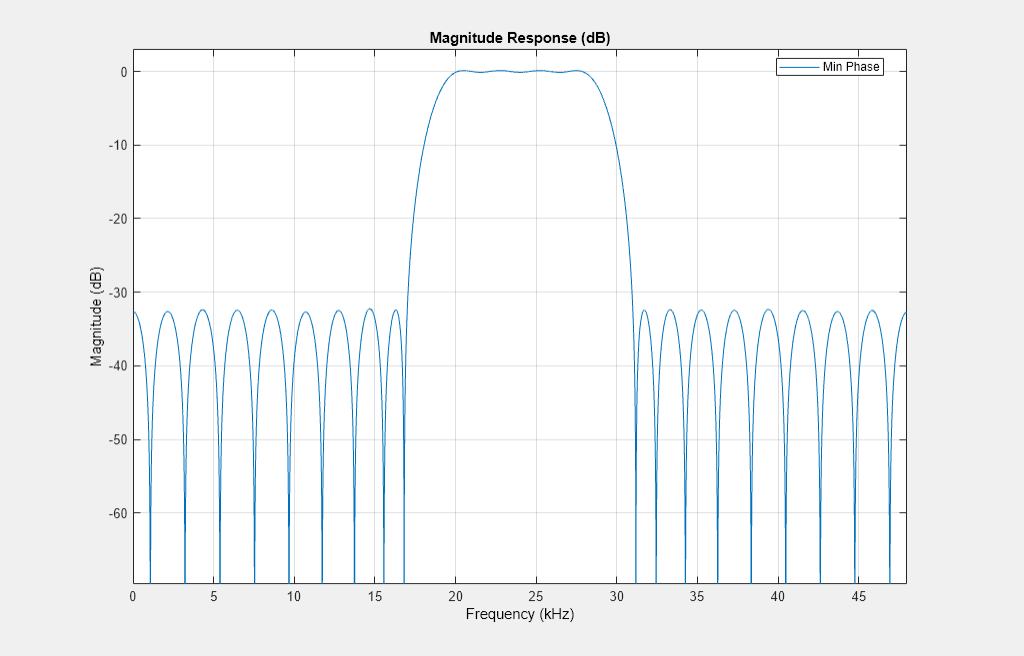
This example illustrates how to generate HDL code for a minimum phase FIRT filter with 10-bit input data. This is a bandpass filter with sample rate of 96 kHz and passband from approximately 19 kHz to 29 kHz. This type of filter is commonly used in feedback loops where linear phase is not sufficient and minimum phase or as close as is achievable is required.
Set up the Coefficients
Design the filter using firgr, which uses the generalized Remez design method. Use the minphase argument to the firgr function to force a minimum phase filter design. Then, use fvtool to visualize the filter response.
Fs  = 96000;
Fn  = Fs/2;
f   = [0 17000 20000 28000 31000 Fn]/Fn;
a   = [0     0     1     1     0  0];
w   = [5 1 5];
b   = firgr(44, f, a, w, 'minphase');
hfvt = fvtool(b,'Fs', Fs,...
              'MagnitudeDisplay', 'Magnitude (dB)',...
              'legend','on');
legend(hfvt,'Min Phase');
Examine the Phase Response
Check the phase response of the filter.
hfvt = fvtool(b,'Fs', Fs,...
              'Analysis', 'phase',...
              'legend','on');
legend(hfvt, 'Min Phase');
Create the Quantized FIRT Fixed-Point Filter
Having checked the minimum phase filter design, construct a FIR filter System object™ with Direct form transposed structure. Set the coefficient word length to 15, and use full precision for the other filter settings.
b_fixed = fi(b,1,15); % use best precision fraction length
T_coeff = numerictype(b_fixed);
minPhaseFilter = dsp.FIRFilter('Structure','Direct form transposed');
minPhaseFilter.Numerator = double(b_fixed);
minPhaseFilter.FullPrecisionOverride = false;
minPhaseFilter.CoefficientsDataType = 'Custom';
minPhaseFilter.CustomCoefficientsDataType = T_coeff;
minPhaseFilter.ProductDataType = 'Full precision';
minPhaseFilter.AccumulatorDataType = 'Full precision';
minPhaseFilter.OutputDataType = 'Same as accumulator';
Check the Fixed-Point Filter Relative to the Reference Design
Check the quantized filter relative to the reference design. The magnitude response is correct but the phase response is no longer min-phase, due to quantization.
hfvt = fvtool(minPhaseFilter, 'Fs', Fs, ...
              'Analysis', 'freq', ...
              'legend', 'on', ...
              'Arithmetic', 'fixed');
legend(hfvt, 'Min Phase');
Check the Impulse Response
Plot the impulse response of the quantized filter. Many of the coefficients have quantized to zero and the overall response still meets the specification, even though the zeros have made the phase response non-minimum. These zeros lead to a smaller implementation because HDL code is not generated for multiplies by zero.
hfvt = fvtool(minPhaseFilter, 'Fs', Fs, ...
              'Analysis', 'Impulse', ...
              'legend', 'on', ...
              'Arithmetic', 'fixed');
legend(hfvt, 'Min Phase');
Generate HDL Code and Test Bench from the Quantized Filter
Starting from the quantized filter, generate VHDL or Verilog.
Create a temporary work directory. After generating the HDL code (Verilog in this case), open the generated file in the editor.
Generate a Verilog test bench to verify that the results match the results in MATLAB. Use the chirp predefined input stimulus.
To generate VHDL code and VHDL test bench instead, change the value for TargetLanguage property from Verilog to VHDL.
Assume an input of 10-bit word length with 9-bit fractional bits.
workingdir = tempname;
generatehdl(minPhaseFilter,'Name', 'hdlminphasefilt', ...
               'TargetLanguage', 'Verilog', ...
               'GenerateHDLTestbench','on', ...
               'TestBenchStimulus', 'chirp', ...
               'TargetDirectory', workingdir, ...
               'InputDataType', numerictype(1,10,9));
### Starting Verilog code generation process for filter: hdlminphasefilt
### Starting Verilog code generation process for filter: hdlminphasefilt
### Generating: C:\Users\nhunting\AppData\Local\Temp\tp7a3c4d2a_0c90_4d74_9e63_ae40e335e80e\hdlminphasefilt.v
### Starting generation of hdlminphasefilt Verilog module
### Starting generation of hdlminphasefilt Verilog module body
### Successful completion of Verilog code generation process for filter: hdlminphasefilt
### HDL latency is 2 samples
### Starting generation of VERILOG Test Bench.
### Generating input stimulus
### Done generating input stimulus; length 1069 samples.
### Generating Test bench: C:\Users\nhunting\AppData\Local\Temp\tp7a3c4d2a_0c90_4d74_9e63_ae40e335e80e\hdlminphasefilt_tb.v
### Creating stimulus vectors ...
### Done generating VERILOG Test Bench.
edit(fullfile(workingdir, 'hdlminphasefilt.v'));Plot the Test Bench Stimulus and the Filter Response
Plot the filter input stimulus and output response on separate plots.
x = generatetbstimulus(minPhaseFilter,'TestBenchStimulus','chirp','InputDataType', numerictype(1,10,9));
xrange = (0:length(x) - 1).*( Fn / (length(x) - 1))/1e3;
y = minPhaseFilter(x.');
subplot(2,1,1); plot(xrange, x); ylim(ylim.*1.1);
axis([0,50,-1.2,1.2]);
title('HDL Min Phase Filter Chirp Stimulus.');
xlabel('Frequency in kHz');
subplot(2,1,2); plot(xrange, y); ylim(ylim.*1.1);
axis([0,50,-1.2,1.2]);
title('HDL Min Phase Filter Response.');
xlabel('Frequency in kHz');

Conclusion
You designed a minimum phase filter and then converted it to a FIR filter System object with transposed structure. You then generated Verilog code for the filter design and a Verilog test bench to functionally verify the results.
You can use a Verilog simulator, such as ModelSim®, to verify these results.
