2-Position Valve Actuator
(To be removed) Actuator for two-position valves
The Hydraulics (Isothermal) library will be removed in a future release. Use the Isothermal Liquid library instead.
For more information on updating your models, see Upgrading Hydraulic Models to Use Isothermal Liquid Blocks.
Library
Valve Actuators
Description
The 2-Position Valve Actuator block represents an actuator that you can use with directional valves to control their position. This actuator can drive a two-position valve. The block is developed as a data-sheet-based model and all its parameters are generally provided in catalogs or data sheets. The key parameters are the stroke, switch-on, and switch-off times.
The block accepts a physical input signal and produces a physical output signal that can be associated with a mechanical translational or rotational push-pin motion. Connect the block output to the directional valve control port.
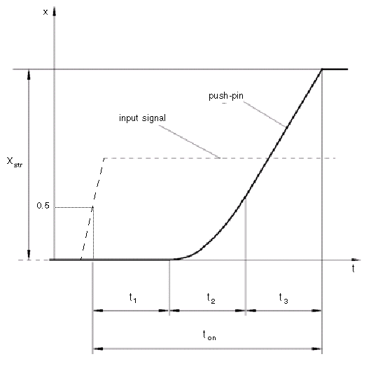
The actuator is represented as an ideal transducer, where output does not depend on the load exerted on the push-pin and the push-pin motion profile remains the same under any loading conditions. The motion profile represents a typical transition curve for electromagnetic actuators and is shown in the following figure:

The push-pin is actuated when the input signal value crosses the threshold of 50% of
the nominal input signal, where Nominal signal value is a block
parameter. The motion is divided into three phases, equal in time: delay
(t1), motion at constant
acceleration (t2), and motion at
constant velocity (t3). The motion
stops when the switch-on time (ton)
elapses. At this moment, the push-pin reaches the specified stroke value
(xstr). To return the push-pin
into initial position, the control signal must cross back through the threshold of 50%
of the nominal input signal, which causes the push-pin to retract. The retract motion
follows exactly the same profile but “stretches” over the switch-off time.
Switching-on time and Switching-off time
are the block parameters.
The transition in any direction can be interrupted at any time by changing the input signal. If motion is interrupted, the switch-on or switch-off times are proportionally decreased depending on the instantaneous push-pin position.
The push-pin is actuated only by positive signal, similar to the AC or DC
electromagnets. The direction of push-pin motion is controlled by the Actuator
orientation parameter, which can have one of two values: Acts in
positive direction or Acts in negative
direction.
Basic Assumptions and Limitations
Push-pin loading, such as inertia, spring, hydraulic forces, and so on, is not taken into account.
Parameters
- Push-pin stroke
The push-pin stroke. The default value is
0.01m.- Switching-on time
Time necessary to fully extend the push-pin after the control signal is applied. The default value is
0.1s.- Switching-off time
Time necessary to retract push-pin from fully extended position after the input signal is removed. The default value is
0.1s.- Nominal signal value
Sets the value of the nominal input signal. The output motion is initiated as the input signal crosses 50% value of the nominal signal. Other than that, the input signal has no effect on the motion profile. This parameter is meant to reproduce the rated voltage feature of an electromagnet. The default value is
24.- Initial position
Specifies the initial position of the push-pin. The parameter can have one of two values:
ExtendedorRetracted. The default value isRetracted.In selecting the initial position, consider the following:
The steady-state push-pin position always corresponds to the control signal. In other words, zero or negative signal keeps the push-pin at
Retracted, and positive signal — atExtended.At the start of simulation, if there is a discrepancy between the initial position of the push-pin, as specified by the Initial position parameter, and the control signal, the push-pin immediately starts moving towards the steady-state position designated by the control signal.
- Actuator orientation
Parameter controls the direction of the push-pin motion and can have one of two values:
Acts in positive directionorActs in negative direction. The first value causes the push-pin to move in positive direction, similarly to the action of electromagnet A attached to a directional valve. If the parameter is set toActs in negative direction, the control signal causes the push-pin to move in negative direction from the initial position. The default value isActs in positive direction.
Ports
The block has one physical signal input port, associated with the input signal, and one physical signal output port, associated with the output signal (push-pin displacement).

