3-Way Directional Valve
(To be removed) Three-port two-position directional control valve
The Hydraulics (Isothermal) library will be removed in a future release. Use the Isothermal Liquid library instead.
For more information on updating your models, see Upgrading Hydraulic Models to Use Isothermal Liquid Blocks.

Libraries:
Simscape /
Fluids /
Hydraulics (Isothermal) /
Valves /
Directional Valves
Description
The 3-Way Directional Valve block represents a directional control valve with three ports and two positions, or flow paths. The ports connect to what in a typical model are a hydraulic pump (port P), a storage tank (port T), and a single-acting actuator (port A). Fluid can flow from the pump to the actuator via path P-A and from the actuator to the tank via path A-T.
Typical Valve Setup
In the default configuration, one valve position corresponds to the A-T flow path maximally open and the P-A flow path maximally closed (position I in the figure). The second valve position corresponds to the P-A flow path maximally open and the A-T flow path maximally closed (position II in the figure). A translating spool serves as the valve control member and determines the position that the valve is in—I, II, or in between.
Valve Positions
Physical signal port S controls the spool displacement. In the default configuration, a zero displacement corresponds to a fully closed valve between positions I and II. A negative displacement shifts the spool toward valve position I. A positive displacement signal shifts the spool toward valve position II. The spool displacement acts indirectly by setting the spool position relative to each flow path—a length known here as the orifice opening. The orifice opening in turn determines the opening area of the respective flow path.
Orifice Openings and Offsets
The orifice opening of a flow path depends partly on its opening offset—the orifice opening of a flow path at zero spool displacement. The block models only the dynamic effects of the opening offsets. An offset can be due to a change in distance between ports or spool lands—the thick disks built into the spool to obstruct flow. It can also be due to a change in the thicknesses of the spool lands. The orifice openings are computed separately for each flow path in terms of the respective opening offset:
where:
hPA and hAT are the orifice openings of the P-A and A-T flow paths. The orifice openings are computed during simulation.
hPA0 and hAT0 are the opening offsets of the P-A and A-T flow paths. The opening offsets are specified in the Valve opening offsets tab.
x is the spool displacement relative to what in the zero-offset case is a fully closed valve. The spool displacement is specified through physical signal port S.
The figure shows the effects of the opening offsets on the orifice openings. Plot I corresponds to the default configuration with both opening offsets equal to zero. Plot II corresponds to a valve with both opening offsets greater than zero and plot III to a valve with both opening offsets smaller than zero. These cases are similar in behavior to zero-lapped (I), underlapped (II) and overlapped (III) valves. The valve schematics to the right show what the offsets might look like for the A-T flow path.
Zero (I), Positive (II), and Negative (III) Opening Offsets
An underlapped valve is always partially open and allows some flow at all spool displacements. An overlapped valve is fully closed over an extended range of spool displacements and requires longer spool travel to open. The table summarizes the opening offsets for zero-lapped, underlapped, and overlapped valves. Other configurations are possible—e.g., with one opening offset positive and the other negative.
| Valve Lapping | Opening Offsets |
|---|---|
| Zero-lapped (default) | Both zero |
| Underlapped | Both positive |
| Overlapped | Both negative |
Opening Area Parameterizations
The Model parameterization setting determines the
calculations used for the opening areas of the flow paths—or, in the
Pressure-flow characteristic case, the volumetric
flow rates. The calculations are based on orifice parameters or tabulated data sets
specified in the Model Parameterization tab. The block uses the
same data for both flow paths if the Area characteristics
parameter in the Basic Parameters tab is set to
Identical for all flow paths and different data
otherwise. Model parameterizations that you can select include:
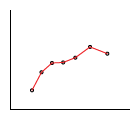
Maximum area and opening— Specify the maximum opening area and the corresponding orifice opening. The opening area is a linear function of the orifice opening,where A is the opening area and h the orifice opening of a given flow path. The subscript
Maxrefers to a fully open orifice and the subscriptLeakto a fully closed orifice—one with internal leakage flow area only. The figure shows a plot of the linear function A(h).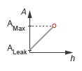
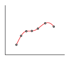
Area vs. opening table— Specify the opening area at discrete orifice openings as a 1-D lookup table. The opening area is computed for a given orifice opening by interpolation or extrapolation of the tabulated data. The figure shows a conceptual plot of the tabulated function A(h).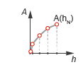
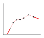
Pressure-flow characteristic— Specify the volumetric flow rate at discrete orifice openings and pressure differentials as a 2-D lookup table. The opening area is computed for a given orifice opening and pressure differential by interpolation or extrapolation of the tabulated data. The figure shows a conceptual plot of the tabulated function q(h, p).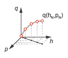
Volumetric flow rates are computed analytically in the Maximum
area and opening and Area vs. opening
table parameterizations. The calculations are based on
additional block parameters such as the flow discharge coefficient and account
for the effects of flow regime—laminar or turbulent. Regime transition
occurs at the specified critical laminar flow ratio or critical Reynolds number.
The Maximum area and opening and Area
vs. opening table parameterizations also account for a small
leakage area associated with the valve spool-to-bore clearance. The leakage area
ensures that portions of the hydraulic network never become isolated when a flow
path is closed. Isolated, or “hanging”, network portions affect
computational efficiency and can cause simulation to fail.
The effects of flow regime and internal leakage are assumed to be reflected in
the tabulated flow rate data specified directly in the
Pressure-flow characteristic
parameterization.
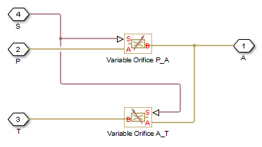
Structural Component Diagram
The block is a composite component with two Variable Orifice blocks driven by a
single physical signal. Block Variable Orifice P_A represents the
P-A flow path. Block Variable orifice
A_T represents the A-T flow path. The physical
signal is specified through Connection Port block S.
The Orifice orientation block parameters are set so that a
positive signal acts to open Variable Orifice P_A while closing
Variable Orifice A_T. A negative signal has the
opposite effect, acting to open Variable Orifice A_T while
closing Variable Orifice P_A.
Valve Structural Diagram
Assumptions
Fluid inertia is ignored.
Spool loading due to inertial, spring, and other forces is ignored.
All valve orifices are assumed identical in size unless otherwise specified.
Ports
Input
Conserving
Parameters
Basic Parameters
Choice of different or identical flow path opening characteristics. Select
Different for each flow path to specify flow
path parameters or tabulated data separately for each flow path.
Parameterization of the valve model. Options include:
By maximum area and opening— Specify the maximum orifice opening and opening area. The opening area varies linearly with the spool displacement specified at physical signal port S.By area vs. opening table— Specify the flow path opening area at discrete orifice openings as a 1-D lookup table. The opening area is computed by interpolation or extrapolation of the tabulated data.By pressure-flow characteristic— Specify the flow path volumetric flow rates at discrete orifice openings and pressure differentials. The flow rate is computed by interpolation or extrapolation of the tabulated data.
Method of computing values inside the tabulated data range. The
Linear method joins adjacent data points with
straight line or surface segments with generally discontinuous slope at the
segment boundaries. Surface segments are used in the 2-D lookup table
specified in the Pressure-flow characteristic
model parameterization.
The Smooth method replaces the straight
segments with curved versions that have continuous slope everywhere inside
the tabulated data range. The segments form a smooth line or surface passing
through all of the tabulated data points without the discontinuities in
first-order derivatives characteristic of the Linear
interpolation method.
Dependencies
This parameter is active when the Model
Parameterization parameter is set to By area
vs. opening table or Pressure-flow
characteristic.
Method of computing values outside of the tabulated data range. The
Linear method extends the line segment drawn between
the last two data points at each end of the data range outward with a
constant slope.
The Nearest method extends the last data point
at each end of the data range outward as a horizontal line with constant value.
Dependencies
This parameter is active when the Model
Parameterization parameter is set to By area
vs. opening table or Pressure-flow
characteristic.
Ratio of the actual and theoretical flow rates through the valve. This parameter depends on the geometrical properties of the valve. Values are usually provided in textbooks and manufacturer data sheets.
Dependencies
This parameter is active when the Model
Parameterization parameter is set to By
maximum area and opening or By area vs.
opening table.
Total area of internal leaks in the completely closed state. The purpose of this parameter is to maintain the numerical integrity of the fluid network by preventing a portion of that network from becoming isolated when the valve is completely closed.
Dependencies
This parameter is active when the Model
Parameterization parameter is set to By
maximum area and opening or By area vs.
opening table.
Select the parameter to base the laminar-turbulent transition on. Options include:
Pressure ratio— Flow transitions between laminar and turbulent at the pressure ratio specified in the Laminar flow pressure ratio parameter. Use this option for the smoothest and most numerically robust flow transitions.Reynolds number— The transition occurs at the Reynolds number specified in the Critical Reynolds number parameter. Flow transitions are more abrupt and can cause simulation issues at near-zero flow rates.
Dependencies
This parameter is active when the Model
Parameterization parameter is set to By
maximum area and opening or By area vs.
opening table.
Pressure ratio at which the flow transitions between the laminar and turbulent regimes. The pressure ratio is the fraction of the outlet pressure over the inlet pressure.
Dependencies
This parameter is active when the Model
Parameterization parameter is set to By
maximum area and opening or By area vs.
opening table and the Laminar transition
specification parameter is set to Pressure
ratio.
Maximum Reynolds number for laminar flow. This parameter depends on the
orifice geometrical profile. You can find recommendations on the parameter
value in hydraulics textbooks. The default value, 12,
corresponds to a round orifice in thin material with sharp edges.
Dependencies
This parameter is active when the Model
Parameterization parameter is set to By
maximum area and opening or By area vs.
opening table and the Laminar transition
specification parameter is set to Reynolds
number.
Model Parameterization: Maximum area and opening
Orifice opening at which the opening area of a flow path is a maximum. The maximum opening is the same for all flow paths when this parameter is exposed. For the orifice opening definitions, see Orifice Openings and Offsets.
Dependencies
This parameter is active when the Area
characteristics parameter is set to
Identical for all flow paths and the
Model parameterization parameter is set to
Maximum area and opening.
Maximum cross-sectional area of a flow path. The maximum opening areas are the same for all paths when this parameter is exposed. For the opening area calculations, see Opening Area Parameterizations.
Dependencies
This parameter is active when the Area
characteristics parameter is set to
Identical for all flow paths and the
Model parameterization parameter is set to
Maximum area and opening.
Spool position relative to the P-A flow path at which the P-A opening area is equal to the P-A, maximum opening area parameter.
Dependencies
This parameter is active when the Area
characteristics parameter is set to
Different for each flow path and the
Model parameterization parameter is set to
Maximum area and opening.
Maximum cross-sectional area of the P-A flow path. The maximum opening areas are different for each flow path when this parameter is exposed. For the opening area calculations, see Opening Area Parameterizations.
Dependencies
This parameter is active when the Area
characteristics parameter is set to
Different for each flow path and the
Model parameterization parameter is set to
Maximum area and opening.
Spool position relative to the A-T flow path at which the A-T opening area is equal to the A-T, maximum opening area parameter.
Dependencies
This parameter is active when the Area
characteristics parameter is set to
Different for each flow path and the
Model parameterization parameter is set to
Maximum area and opening.
Maximum cross-sectional area of the P-A flow path. The maximum opening areas are different for each flow path when this parameter is exposed. For the opening area calculations, see Opening Area Parameterizations.
Dependencies
This parameter is active when the Area
characteristics parameter is set to
Different for each flow path and the
Model parameterization parameter is set to
Maximum area and opening.
Model Parameterization: Area vs. opening table
Array of orifice openings used to construct the opening area 1-D lookup table for all flow paths. The opening characteristics are identical for all flow paths when this parameter is exposed. The number of elements in the array determines the number of columns in the table.
The array must increase from left to right but the intervals between the
array element values need not be uniform. There must be at least two
elements for Linear interpolation and three
elements for Smooth interpolation.
Dependencies
This parameter is active when the Area
characteristics parameter is set to
Identical for all flow paths and the
Model parameterization parameter is set to
Area vs. opening table.
Array of flow path opening areas corresponding to the specified orifice openings. The number of elements in the array must match the number of elements in the Opening vector parameter.
Dependencies
This parameter is active when the Area
characteristics parameter is set to
Identical for all flow paths and the
Model parameterization parameter is set to
Area vs. opening table.
Array of P-A orifice openings used to construct the opening area 1-D lookup table for the P-A flow path. The number of elements in the array determines the number of elements in the table.
The array must increase from left to right but the intervals between the
array element values need not be uniform. There must be at least two
elements for Linear interpolation and three
elements for Smooth interpolation.
Dependencies
This parameter is active when the Area
characteristics parameter is set to
Different for each flow path and the
Model parameterization parameter is set to
Area vs. opening table.
Array of P-A opening areas corresponding to the specified P-A orifice openings. The number of elements in the array must match the number of elements in the P-A, opening vector parameter.
Dependencies
This parameter is active when the Area
characteristics parameter is set to
Different for each flow path and the
Model parameterization parameter is set to
Area vs. opening table.
Array of A-T orifice openings used to construct the opening area 1-D lookup table for the A-T flow path. The number of elements in the array determines the number of elements in the table.
Dependencies
This parameter is active when the Area
characteristics parameter is set to
Different for each flow path and the
Model parameterization parameter is set to
Area vs. opening table.
Array of A-T opening areas corresponding to the specified A-T orifice openings. The number of elements in the array must match the number of elements in the A-T, opening vector parameter.
Dependencies
This parameter is active when the Area
characteristics parameter is set to
Different for each flow path and the
Model parameterization parameter is set to
Area vs. opening table.
Model Parameterization: Pressure-flow characteristic
Array of orifice openings used to construct the volumetric flow rate 2-D
lookup table. The number of elements in the array determines the number of
rows in the table. The array must increase from left to right but the
intervals between the array element values need not be uniform. There must
be at least two elements for Linear interpolation
and three elements for Smooth
interpolation.
Dependencies
This parameter is active when the Area
characteristics parameter is set to
Identical for all flow paths and the
Model parameterization parameter is set to
Pressure-flow
                                characteristic
.
Array of pressure differentials used to construct the volumetric flow rate
2-D lookup table. The number of elements in the array determines the number
of columns in the table. The array must increase from left to right but the
intervals between the array element values need not be uniform. There must
be at least two elements for Linear interpolation
and three elements for Smooth
interpolation.
Dependencies
This parameter is active when the Area
characteristics parameter is set to
Identical for all flow paths and the
Model parameterization parameter is set to
Pressure-flow
                                characteristic
.
Matrix with the volumetric flow rates corresponding to the specified orifice openings and pressure differentials. The number of rows must match the number of elements in the Opening vector, s parameter. The number of columns must match the number of elements in the Pressure differential vector, dp parameter.
Dependencies
This parameter is active when the Area
characteristics parameter is set to
Identical for all flow paths and the
Model parameterization parameter is set to
Pressure-flow characteristic.
Array of P-A orifice openings used to construct the
P-A volumetric flow rate 2-D lookup table. The
number of elements in the array determines the number of rows in the table.
The array must increase from left to right but the intervals between the
array element values need not be uniform. There must be at least two
elements for Linear interpolation and three
elements for Smooth interpolation.
Dependencies
This parameter is active when the Area
characteristics parameter is set to
Different for each flow path and the
Model parameterization parameter is set to
Pressure-flow characteristic.
Array of pressure differentials used to construct the volumetric flow rate 2-D lookup table for the P-A flow path. The number of elements in the array determines the number of columns in the table.
The array must increase from left to right but the intervals between the
array element values need not be uniform. There must be at least two
elements for Linear interpolation and three
elements for Smooth interpolation.
Dependencies
This parameter is active when the Area
characteristics parameter is set to
Different for each flow path and the
Model parameterization parameter is set to
Pressure-flow characteristic.
Matrix with the volumetric flow rates through the P-A flow path at the P-A orifice openings and pressure differentials. The number of rows must match the number of elements in the P-A, opening vector, s parameter. The number of columns must match the number of elements in the P-A, pressure differential vector, dp parameter.
Dependencies
This parameter is active when the Area
characteristics parameter is set to
Different for each flow path and the
Model parameterization parameter is set to
Pressure-flow characteristic.
Array of A-T orifice openings used to construct the A-T volumetric flow rate 2-D lookup table. The number of elements in the array determines the number of rows in the table.
The array must increase from left to right but the intervals between the
array element values need not be uniform. There must be at least two
elements for Linear interpolation and three
elements for Smooth interpolation.
Dependencies
This parameter is active when the Area
characteristics parameter is set to
Different for each flow path and the
Model parameterization parameter is set to
Pressure-flow characteristic.
Array of pressure differentials used to construct the volumetric flow rate 2-D lookup table for the A-T flow path. The number of elements in the array determines the number of columns in the table.
The array must increase from left to right but the intervals between the
array element values need not be uniform. There must be at least two
elements for Linear interpolation and three
elements for Smooth interpolation.
Dependencies
This parameter is active when the Area
characteristics parameter is set to
Different for each flow path and the
Model parameterization parameter is set to
Pressure-flow characteristic.
Matrix with the volumetric flow rates through the A-T flow path at the A-T orifice openings and pressure differentials. The number of rows must match the number of elements in the A-T, opening vector, s parameter. The number of columns must match the number of elements in the A-T, pressure differential vector, dp parameter.
Dependencies
This parameter is active when the Area
characteristics parameter is set to
Different for each flow path and the
Model parameterization parameter is set to
Pressure-flow characteristic.
Valve Opening Offsets
Orifice opening of the P-A flow path at zero spool
displacement. Specify a positive offset to model an underlapped valve or a
negative offset to model an overlapped valve. The default value of
0 corresponds to a zero-lapped valve.
Orifice opening of the A-T flow path at zero spool
displacement. Specify a positive offset to model an underlapped valve or a
negative offset to model an overlapped valve. The default value of
0 corresponds to a zero-lapped valve.