4-Way 2-Position Directional Valve (2P)
R2026b4-Way 2-Position Directional Valve (2P) block

To add a block to a model, double-click the canvas and start typing the block name. Then, select the block from the list.
Libraries:
Simscape /
Fluids /
Two-Phase Fluid /
Valves & Orifices /
Directional Control Valves
Description
The 4-Way 2-Position Directional Valve (2P) models a valve with four openings — such as the valves between an actuator, pump, and tank — in a two-phase fluid network. A single spool controls the valve operation according to the signal at port S. You can set the baseline configuration of your valve by specifying the orifices that are open when the spool moves in the positive direction and negative directions in the Positive spool position open connections and Negative spool position open connections parameters, respectively. You can set the valve opening model in the Orifice parameterization parameter as a linear relationship or function of user-provided data, which you can apply to one or all flow paths in the valve.
This block is a composite component that comprises of multiple instances of the Orifice (2P) block. Refer to the Orifice (2P) block for more details about valve parameterizations and block calculations. In some configurations, this valve resembles a 3-way valve. To set additional flow paths when the spool is in the neutral position, see the 4-Way 3-Position Directional Valve (2P) block.
This image shows an example valve setup where the valve is connected to a tank,
actuator, and pump and the Positive spool position open connections
parameter is P-B, A-T:
This image shows the valve when the Negative spool position open
connections parameter is P-A, B-T:
In this configuration, when the signal at port S moves the spool to a negative position, the paths between ports P and A and between ports B and T are open to flow. The paths between ports P and B and ports A and T are closed to flow.
This image shows the valve when the Positive spool position open
connections parameter is P-B, A-T:
In this configuration, when the signal at port S moves the spool to a positive position, the paths between ports P and B and between ports A and T are open to flow and the paths between ports P and A and between ports B and T are closed.
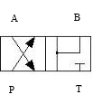
The schematic that represents this configuration is:
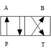
The left-hand side corresponds to the positive position and the right-hand side corresponds to the negative position. The valve transitions through positions in the neutral mid-section.
Spool Displacement and Valve Configuration
The spool stroke is the amount of spool travel an orifice takes to fully open from a closed position. You can use the Orifice parameterization and Area characteristics parameters to specify the flow path characteristics:
| Orifice Parameterization | Identical for All Flow Paths | Different for Each Flow Path |
|---|---|---|
Linear - Area vs. spool
travel | The Spool travel between closed and open orifice parameter defines the spool stroke | The Spool travel between closed and open orifice parameter defines the spool stroke for each orifice |
Tabulated data - Area vs. spool
travel | The difference between the first and last element of the Spool travel vector parameter defines the spool stroke | The difference between the first and last element of the Spool travel vector parameter for each orifice |
Tabulated data - Volumetric flow rate vs. spool
										travel and pressure drop
or
Tabulated data - Mass flow rate vs. spool
travel and pressure drop | The difference between the first and last element of the Spool travel vector, ds parameter defines the spool stroke | The difference between the first and last element of the Spool travel vector, ds parameter defines the spool stroke for each orifice |
The direction of the spool movement depends on the spool stroke, orifice orientation, and signal at port S. This table shows the spool travel for an orifice depending on the selections for the Positive spool position open connection and Negative spool position open connection parameters:
| Spool Position When Orifice Is Open | Spool Travel, ΔS |
|---|---|
| Orifice always closed: orifice not selected for the Positive spool position open connection or Negative spool position open connection parameters | N/A |
| Orifice always open: orifice selected for both the Positive spool position open connection and Negative spool position open connection parameters | N/A |
| Negative: orifice selected for only Negative spool position open connection parameter | Sorifice_max + spool stroke – S |
| Positive: orifice selected for only Positive spool position open connection parameter | Sorifice_max – spool stroke + S |
Where Sorifice_max is the spool position at the maximum orifice area defined for each orifice. The orifice area saturates at the leakage area when ΔS is negative and saturates at the maximum orifice area when the orifice is fully open. When the orifice is fully open, ΔS is equal to the spool stroke, so ΔS greater than the spool stroke does not further increase the orifice area.
This table shows the possible configurations of the 4-Way 2-Position Directional Valve (TL):
| Configuration | Parameter Values |
|---|---|
All four paths are closed during transition. |
|
All four paths are open during transition. |
|
A-T and B-T are closed during transition. |
|
P-A and P-B are closed during transition. |
|
P-B and B-T are closed during transition. |
|
P-A and A-T are closed during transition. |
|
P-A, P-B, and B-T are open during transition. |
|
P-A, A-T, and B-T are open during transition. |
|
P-A and P-B are closed during transition. A-T is always closed. |
|
All paths are closed during transition. |
|
A-T is open during transition. P-A is closed during transition. |
|
B-T is open during transition. P-B is closed during transition. |
|
P-A is closed during transition. |
|
P-B is closed during transition. |
|
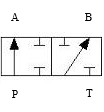
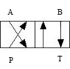
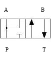


Valve Orifice Parameterizations
The Modeling option parameter controls the parameterization options for a valve designed for modeling either vapor or liquid, but does not impact the fluid properties. The block calculates fluid properties inside the valve from inlet conditions.
The Orifice parameterization parameter specifies the model
for the open area or flow rate through one or all of the valve orifices. If you set
Area characteristics to Identical for all flow
paths, the block applies the same data for all flow paths. When
you select Different for all flow paths, the block uses
individual parameterizations for each flow path.
When Modeling option is Liquid operating
condition, the block parameterizations are designed for a
valve controlling liquid flow.
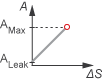
When Orifice parameterization is Linear -
Area vs. spool travel, the opening area is a linear function
of the spool position received as a signal at port S
where:
ΔS is the spool travel.
Aorifice saturates at Aleak when ΔS is negative and saturates at Amax when the orifice is fully open. When the orifice is fully open, ΔS is equal to the spool stroke, so a value of ΔS that is greater than the spool stroke does not increase the orifice area.
ΔSmax is the value of the Spool travel between closed and open orifice parameter.
Amax is the value of the Maximum orifice area parameter.
Aleak is the value of the Leakage area parameter.
When the valve is in a near-open or near-closed position in the linear parameterization, you can maintain numerical robustness in your simulation by adjusting the Smoothing factor parameter. If the Smoothing factor parameter is nonzero, the block smoothly saturates the opening area between Aleak and Amax. For more information, see Numerical Smoothing.
When Orifice parameterization is Tabulated data - Area
vs. spool travel, you can provide spool travel vectors for
your system or for individual flow paths between ports P,
A, B, and T.
The block uses this data to calculate the relationship between the orifice area
and spool displacement. The block uses interpolation to determine the opening
area between given data points. Aleak
and Amax are the first and last
parameters of the opening area vector, respectively.
When Orifice parameterization is Tabulated
data - Nominal mass flow rate vs. spool travel, the block
calculates the mass flow rate for each orifice from the nominal conditions you
specify in the block parameters. The spool position signal from port
S scales the orifice opening area, which can also scale
mass flow rate.
When Modeling option is Vapor operating
condition, the block parameterizations are designed to model a
valve that controls vapor flow.
The method the block uses to control each orifice depends on the Opening characteristic parameter:
Linear— The measure of flow capacity depends on the spool position at port S. As the spool displaces to open to orifice, the measure of flow capacity scales from the specified minimum to the specified maximum.Tabulated— The block calculates the measure of flow capacity as a function of the spool position at port S. This function uses a one-dimensional lookup table.
The Orifice parameterization parameter determines how the block calculates the flow rate in each orifice:
Cv flow coefficient— The flow coefficient Cv scales the flow rate in each orifice. The flow coefficient measures the ease with which a fluid can flow when driven by a certain pressure differential.Kv flow coefficient— The flow coefficient Kv, where , scales the flow rate in each orifice. The flow coefficient measures the ease with which a fluid can flow when driven by a certain pressure differential.Orifice area— The size of the orifice area scales the flow rate in each orifice.
Visualize Orifice Openings
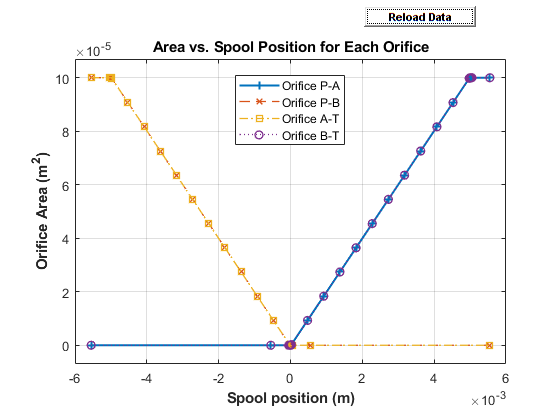
To generate a characteristic plot of the valve, click the Plot button next to Valve characteristics. The plot shows the orifices specified by the parameters in Valve Configuration section. When you set the parameters in the Valve Configuration tab to the same orifice, the orifice opening is a constant.
Click Reload Data to update the data in the figure.
This image shows the default configuration for the block:
Positive spool position open connections is
P-A,
												B-T
Negative spool position open connections is
P-B,
												A-T
All other spool positions are at the default values.
Assumptions and Limitations
There is no heat exchange between the valve and the environment.
When Modeling option is
Liquid operating condition, the results may not be accurate outside of the subcooled liquid region. When Modeling option isVapor operating condition, the results may not be accurate outside of the superheated vapor region. To model a valve in a liquid-vapor mixture, set Modeling option toLiquid operating condition.
Ports
Conserving
Two-phase fluid conserving port associated with the entry or exit port to the valve.
Programmatic Use
Port:
A
Two-phase fluid conserving port associated with the entry or exit port to the valve.
Programmatic Use
Port:
B
Two-phase fluid conserving port associated with the entry or exit port to the valve.
Programmatic Use
Port:
P
Two-phase fluid conserving port associated with the entry or exit port to the valve.
Programmatic Use
Port:
T
Input
Physical signal associated with the spool displacement, in m.
Programmatic Use
Port:
S
Parameters
Modeling option for the fluid phase at the valve. Set this parameter to
Liquid operating condition if the two-phase
fluid at the block location is in a liquid state. Set this parameter to
Vapor operating condition if the two-phase
fluid at the block location is in a vapor state.
Programmatic Use
| Parameter: | ComponentPath |
| Values: | "fluids.two_phase_fluid.valves_orifices.directional_control_valves.directional_valve_4_way_2_position_liquid" | "fluids.two_phase_fluid.valves_orifices.directional_control_valves.directional_valve_4_way_2_position_vapor" |
Valve Configuration
Flow paths open when the spool is in a positive position. This parameter sets the valve configuration and defines the direction of spool movement according to the signal received at port S.
Programmatic Use
| Parameter: | open_orifices_pos |
| Values: | "fluids.two_phase_fluid.valves_orifices.directional_control_valves.enum.OpenOrifices4Way2Position.PA_BT" | "fluids.two_phase_fluid.valves_orifices.directional_control_valves.enum.OpenOrifices4Way2Position.PA_PB" | "fluids.two_phase_fluid.valves_orifices.directional_control_valves.enum.OpenOrifices4Way2Position.PB_AT" | "fluids.two_phase_fluid.valves_orifices.directional_control_valves.enum.OpenOrifices4Way2Position.PA" | "fluids.two_phase_fluid.valves_orifices.directional_control_valves.enum.OpenOrifices4Way2Position.PB" | "fluids.two_phase_fluid.valves_orifices.directional_control_valves.enum.OpenOrifices4Way2Position.PA_PB_AT_BT" | "fluids.two_phase_fluid.valves_orifices.directional_control_valves.enum.OpenOrifices4Way2Position.AllClosed" |
Flow paths open when the spool moves in the negative direction. This parameter sets the valve configuration and defines the direction of spool movement according to the signal received at port S.
Programmatic Use
| Parameter: | open_orifices_neg |
| Values: | "fluids.two_phase_fluid.valves_orifices.directional_control_valves.enum.OpenOrifices4Way2Position.PB_AT" | "fluids.two_phase_fluid.valves_orifices.directional_control_valves.enum.OpenOrifices4Way2Position.PA_BT" | "fluids.two_phase_fluid.valves_orifices.directional_control_valves.enum.OpenOrifices4Way2Position.PA_PB" | "fluids.two_phase_fluid.valves_orifices.directional_control_valves.enum.OpenOrifices4Way2Position.PA" | "fluids.two_phase_fluid.valves_orifices.directional_control_valves.enum.OpenOrifices4Way2Position.PB" | "fluids.two_phase_fluid.valves_orifices.directional_control_valves.enum.OpenOrifices4Way2Position.PA_PB_AT_BT" | "fluids.two_phase_fluid.valves_orifices.directional_control_valves.enum.OpenOrifices4Way2Position.AllClosed" |
Model Parameterization
Whether to apply uniform or individual flow equations for the valve
orifice area. When you set this parameter to Identical for
all flow paths, the block uses the same orifice and
spool geometries, flow rates, pressure, and area vectors for all valve
orifices. When you set this parameter to Different for each
flow path, you can specify these parameters
individually for each orifice. For both settings, orifices
A, B,
P, and T have the same
cross-sectional areas, discharge coefficients, and Reynolds numbers when
you set Orifice parameterization to
Linear - Area vs. spool travel or
Tabulated data - Area vs. spool travel.
Programmatic Use
| Parameter: | area_spec |
| Values: | "fluids.two_phase_fluid.valves_orifices.directional_control_valves.enum.AreaSpec.Identical" | "fluids.two_phase_fluid.valves_orifices.directional_control_valves.enum.AreaSpec.Different" |
Method the block uses to calculate the mass flow rate from the pressure difference across the orifice or the pressure difference from the mass flow rate.
When Modeling option is Liquid
operating condition, the choices for this parameter are:
Linear - Area vs. spool travelLinear - Nominal mass flow rate vs. spool travelTabulated data - Area vs. spool travel
When Modeling option is Vapor
operating condition, the choices for this parameter are:
Cv flow coefficientKv flow coefficientOrifice area
Programmatic Use
| Parameter: | liquid_valve_parameterization |
| Values: | "fluids.two_phase_fluid.valves_orifices.directional_control_valves.enum.LiquidOrificeParameterization.LinearArea" | "fluids.two_phase_fluid.valves_orifices.directional_control_valves.enum.LiquidOrificeParameterization.LinearNominalMassFlow" | "fluids.two_phase_fluid.valves_orifices.directional_control_valves.enum.LiquidOrificeParameterization.Tabulated1DArea" |
| Parameter: | vapor_valve_parameterization |
| Values: | "fluids.two_phase_fluid.valves_orifices.enum.VaporOrificeParameterization.Cv" | "fluids.two_phase_fluid.valves_orifices.enum.VaporOrificeParameterization.Kv" | "fluids.two_phase_fluid.valves_orifices.enum.VaporOrificeParameterization.Area" |
Maximum distance of spool travel.
Dependencies
To enable this parameter, set Area
characteristics to Identical for all
flow paths and either:
Modeling option to
Liquid operating conditionand Orifice parameterization toLinear - Area vs. spool travel.Modeling option to
Vapor operating conditionand Opening characteristic toLinear.
Programmatic Use
Parameter:
del_S_max
Largest open area of each orifice during the operation of the valve.
Dependencies
To enable this parameter, set Area
characteristics to Identical for all
flow paths and either:
Modeling option to
Liquid operating conditionand Orifice parameterization toLinear - Area vs. spool travel.Modeling option to
Vapor operating condition, Orifice parameterization toOrifice area, and Opening characteristic toLinear.
Programmatic Use
Parameter:
orifice_area_max
Parameter:
valve_area_max
Typical, rated, or design mass flow rate at the orifice maximum opening position.
Dependencies
To enable this parameter, set Modeling option
to Liquid operating condition,
Area characteristics to
Identical for all flow paths, and
Orifice parameterization to
Linear - Nominal mass flow rate vs. spool
travel.
Programmatic Use
Parameter:
mdot_nominal_max
Typical, rated, or design pressure drop at the orifice maximum opening position.
Dependencies
To enable this parameter, set Modeling option
to Liquid operating condition,
Area characteristics to
Identical for all flow paths, and
Orifice parameterization to
Linear - Nominal mass flow rate vs. spool
travel.
Programmatic Use
Parameter:
delta_p_nominal_max
Method of determining the inlet fluid state. The block determines the orifice nominal inlet specific volume from the tabulated fluid properties data based on the value of the Nominal inlet pressure and Nominal inlet condition specification parameters.
Dependencies
To enable this parameter, set Modeling option
to Liquid operating condition,
Area characteristics to
Identical for all flow paths, and
Orifice parameterization to
Linear - Nominal mass flow rate vs. spool
travel.
Programmatic Use
| Parameter: | energy_spec |
| Values: | "foundation.enum.energy_spec.temperature" | "foundation.enum.energy_spec.quality" | "foundation.enum.energy_spec.void_fraction" | "foundation.enum.energy_spec.enthalpy" | "foundation.enum.energy_spec.internal_energy" |
Inlet pressure in nominal conditions. The block determines the inlet specific volume from the tabulated fluid properties data based on the value of the Nominal inlet pressure and Nominal inlet condition specification parameters.
Dependencies
To enable this parameter, set Modeling option
to Liquid operating condition,
Area characteristics to
Identical for all flow paths, and
Orifice parameterization to
Linear - Nominal mass flow rate vs. spool
travel.
Programmatic Use
Parameter:
p_inlet
Inlet fluid temperature in nominal operating conditions.
Dependencies
To enable this parameter, set Modeling option
to Liquid operating condition,
Area characteristics to
Identical for all flow paths,
Orifice parameterization to
Linear - Nominal mass flow rate vs. spool
travel, and Nominal inlet condition
specification to
Temperature.
Programmatic Use
Parameter:
T_inlet
Inlet mixture vapor quality by mass fraction in nominal operating
conditions. A value of 0 means that the inlet fluid
is subcooled liquid. A value of 1 means that the
inlet fluid is superheated vapor.
Dependencies
To enable this parameter, set Modeling option
to Liquid operating condition,
Area characteristics to
Identical for all flow paths,
Orifice parameterization to
Linear - Nominal mass flow rate vs. spool
travel, and Nominal inlet condition
specification to Vapor
quality.
Programmatic Use
Parameter:
x_inlet
Inlet mixture volume fraction in nominal operating conditions. A value
of 0 means that the inlet fluid is subcooled liquid.
A value of 1 means that the inlet fluid is
superheated vapor.
Dependencies
To enable this parameter, set Modeling option
to Liquid operating condition,
Area characteristics to
Identical for all flow paths,
Orifice parameterization to
Linear - Nominal mass flow rate vs. spool
travel, and Nominal inlet condition
specification to Vapor void
fraction.
Programmatic Use
Parameter:
alpha_inlet
Inlet specific enthalpy in nominal operating conditions.
Dependencies
To enable this parameter, set Modeling option
to Liquid operating condition,
Area characteristics to
Identical for all flow paths,
Orifice parameterization to
Linear - Nominal mass flow rate vs. spool
travel, and Nominal inlet condition
specification to Specific
enthalpy.
Programmatic Use
Parameter:
h_inlet
Inlet specific internal energy in nominal operating conditions.
Dependencies
To enable this parameter, set Modeling option
to Liquid operating condition,
Area characteristics to
Identical for all flow paths,
Orifice parameterization to
Linear - Nominal mass flow rate vs. spool
travel, and Nominal inlet condition
specification to Specific internal
energy.
Programmatic Use
Parameter:
u_inlet
Method by which to convert the control signal specified at port S to the chosen measure of flow capacity.
Dependencies
To enable this parameter, set Modeling option
to Vapor operating condition.
Programmatic Use
| Parameter: | opening_characteristic |
| Values: | "fluids.two_phase_fluid.valves_orifices.enum.OpeningCharacteristics.Linear" | "fluids.two_phase_fluid.valves_orifices.enum.OpeningCharacteristics.Tabulated" |
Vector of spool travel distances when parameterizing the orifice according to the tabulated valve area data. The vector elements must correspond one-to-one with the elements in the Orifice area vector parameter. List the values in ascending order. The first element must be 0. The block uses linear interpolation between table data points.
Dependencies
To enable this parameter, set Area
characteristics to Identical for all
flow paths and either:
Modeling option to
Liquid operating conditionand Orifice parameterization toTabulated data - Area vs. spool travel.Modeling option to
Vapor operating conditionand Opening characteristic toTabulated.
Programmatic Use
Parameter:
del_S_Cv_TLU
Parameter:
del_S_Kv_TLU
Parameter:
del_S_orifice_area_TLU
Parameter:
del_S_TLU
Vector of opening areas when parameterizing the orifice according to the tabulated valve area data. The vector elements must correspond one-to-one with the elements in the Spool travel vector parameter. List the values in ascending order. The elements must be greater than 0. The first element of this vector is the leakage area.
Dependencies
To enable this parameter, set Area
characteristics to Identical for all
flow paths and either:
Modeling option to
Liquid operating conditionand Orifice parameterization toTabulated data - Area vs. spool travel.Modeling option to
Vapor operating condition, Orifice parameterization toOrifice area, and Opening characteristic toTabulated.
Programmatic Use
Parameter:
orifice_area_TLU
Parameter:
valve_area_TLU
Value of the Cv flow coefficient when the orifice is fully open and the area available for flow is at a maximum. This parameter measures the ease with which the vapor traverses the resistive element when driven by a pressure differential.
Dependencies
To enable this parameter, set Modeling option
to Vapor operating condition,
Area characteristics to
Identical for all flow paths,
Orifice parameterization to Cv
flow coefficient, and Opening
characteristic to
Linear.
Programmatic Use
Parameter:
Cv_max
Vector of Cv flow coefficients. Each coefficient corresponds to a value in the Control member position vector parameter. This parameter measures the ease with which the vapor traverses the resistive element when driven by a pressure differential. The size of the vector must be the same as the Control member position vector parameter.
Dependencies
To enable this parameter, set Modeling option
to Vapor operating condition,
Area characteristics to
Identical for all flow paths,
Orifice parameterization to Cv
flow coefficient, and Opening
characteristic to
Tabulated.
Programmatic Use
Parameter:
Cv_TLU
Value of the Kv flow coefficient when the orifice is fully open and the area available for flow is at a maximum. This parameter measures the ease with which the vapor traverses the resistive element when driven by a pressure differential.
Dependencies
To enable this parameter, set Modeling option
to Vapor operating condition,
Area characteristics to
Identical for all flow paths,
Orifice parameterization to Kv
flow coefficient, and Opening
characteristic to
Linear.
Programmatic Use
Parameter:
Kv_max
Vector of Kv flow coefficients. Each coefficient corresponds to a value in the Control member position vector parameter. This parameter measures the ease with which the vapor traverses the resistive element when driven by a pressure differential. The size of the vector must be the same as the Control member position vector parameter.
Dependencies
To enable this parameter, set Modeling option
to Vapor operating condition,
Area characteristics to
Identical for all flow paths,
Orifice parameterization to Kv
flow coefficient, and Opening
characteristic to
Tabulated.
Programmatic Use
Parameter:
Kv_TLU
Ratio between the inlet pressure, pin, and the outlet pressure, pout, defined as where choking first occurs.
Dependencies
To enable this parameter, Modeling option to
Vapor operating condition,
Area characteristics to
Identical for all flow paths, and
Orifice parameterization to Cv
flow coefficient or Kv flow
coefficient.
Programmatic Use
Parameter:
xT_Cv
Parameter:
xT_Kv
Correction factor that accounts for discharge losses in theoretical flows.
Dependencies
To enable this parameter, set Modeling option
to Vapor operating condition and
Orifice parameterization to
Orifice area or set
Modeling option to Liquid
operating condition and Orifice
parameterization to either:
Linear - Area vs. spool travelTabulated data - Area vs. spool travel
Programmatic Use
Parameter:
Cd
Ratio of the flow rate of the orifice when it is closed to when it is open.
Dependencies
To enable this parameter, set either:
Modeling option to
Liquid operating conditionand Orifice parameterization toLinear - Area vs. spool travel.Modeling option to
Vapor operating conditionand Opening characteristic toLinear.
Programmatic Use
Parameter:
leakage_fraction
Continuous smoothing factor that introduces a layer of gradual change based on the flow response when the valve is in the near-open and near-closed positions. To increase the stability of your simulation in these regimes, set this parameter to a nonzero value less than one.
Dependencies
To enable this parameter, set Modeling option
to Liquid operating condition and
Orifice parametrization to
Linear - area vs. spool travel or set
Modeling option to Vapor
operating condition and Opening
characteristic to
Linear.
Programmatic Use
Parameter:
smoothing_factor
Whether to account for pressure increase when fluid flows from a region of smaller cross-sectional area to a region of larger cross-sectional area.
Dependencies
To enable this parameter, set Modeling option
to Liquid operating condition and
Orifice parameterization to either:
Linear - area vs. spool travelTabulated data - Area vs. spool travel
Programmatic Use
| Parameter: | pressure_recovery |
| Values: | "true" | "false" |
Ratio of the orifice outlet pressure to orifice inlet pressure at which the fluid transitions between the laminar and turbulent regimes. The pressure loss corresponds to the mass flow rate linearly in laminar flows and quadratically in turbulent flows.
Programmatic Use
Parameter:
B_lam
Time lag for liquid-vapor mixtures when computing the fluid specific volume. This parameter does not influence the specific volume when the inlet fluid is a fully supercooled liquid or fully superheated vapor.
Dependencies
To enable this parameter, set Modeling option
to Liquid operating condition.
Programmatic Use
Parameter:
tau_x
Maximum cross-sectional areas at the entry and exit ports P, T, A, and B, which the block uses in the pressure-flow rate equation that determines the mass flow rate through the valve.
Programmatic Use
Parameter:
area
P-A Orifice
Spool offset from the neutral position for a fully open P-A orifice.
Dependencies
To enable this parameter, set one of these parameters.
Set Positive spool position open connections to:
P-A, B-TP-A, P-BP-AP-A, P-B, A-T, B-T
or set Negative spool position open connections to:
P-A, B-TP-A, P-BP-AP-A, P-B, A-T, B-T
Note:
This parameter is enabled only when the P-A orifice settings do not appear in both the Positive spool position open connections and Negative spool position open connections parameters.
Programmatic Use
Parameter:
S_max_PA
Maximum distance of spool travel. This value provides an upper limit to calculations so that simulations do not return unphysical values.
Dependencies
To enable this parameter, set one of the following parameters:
Positive spool position open connections to:
P-A, B-TP-A, P-BP-AP-A, P-B, A-T, B-T
Negative spool position open connections to:
P-A, B-TP-A, P-BP-AP-A, P-B, A-T, B-T
And either:
Modeling option to
Liquid operating condition, Area characteristics toDifferent for each flow path, and Orifice parameterization toLinear - Area vs. spool travelorLinear - Nominal mass flow rate vs. spool travel.Modeling option to
Vapor operating condition, Area characteristics toDifferent for each flow path, and Opening characteristic toLinear.
Programmatic Use
Parameter:
del_S_max_PA
Typical, rated, or design mass flow rate through a maximally open P-A orifice.
Dependencies
To enable this parameter, set:
Modeling option to
Liquid operating conditionArea characteristics to
Different for each flow pathOrifice parameterization to
Linear - Nominal mass flow rate vs. spool travelOne of the following parameters:
Positive spool position open connections to:
P-A, B-TP-A, P-BP-AP-A, P-B, A-T, B-T
Negative spool position open connections to:
P-A, B-TP-A, P-BP-AP-A, P-B, A-T, B-T
Programmatic Use
Parameter:
mdot_nominal_max_PA
Typical, rated, or design pressure drop through a maximally open P-A orifice.
Dependencies
To enable this parameter, set:
Modeling option to
Liquid operating conditionArea characteristics to
Different for each flow pathOrifice parameterization to
Linear - Nominal mass flow rate vs. spool travelOne of the following parameters:
Positive spool position open connections to:
P-A, B-TP-A, P-BP-AP-A, P-B, A-T, B-T
Negative spool position open connections to:
P-A, B-TP-A, P-BP-AP-A, P-B, A-T, B-T
Programmatic Use
Parameter:
delta_p_nominal_max_PA
Method of determining the inlet fluid state for P-A orifice.
Dependencies
To enable this parameter, set:
Modeling option to
Liquid operating conditionArea characteristics to
Different for each flow pathOrifice parameterization to
Linear - Nominal mass flow rate vs. spool travelAt least one of the following parameters:
Positive spool position open connections to:
P-A, B-TP-A, P-BP-AP-A, P-B, A-T, B-T
Negative spool position open connections to:
P-A, B-TP-A, P-BP-AP-A, P-B, A-T, B-T
Programmatic Use
| Parameter: | energy_spec_PA |
| Values: | "foundation.enum.energy_spec.temperature" | "foundation.enum.energy_spec.quality" | "foundation.enum.energy_spec.void_fraction" | "foundation.enum.energy_spec.enthalpy" | "foundation.enum.energy_spec.internal_energy" |
Inlet pressure for the P-A orifice at nominal conditions.
Dependencies
To enable this parameter, set:
Modeling option to
Liquid operating conditionArea characteristics to
Different for each flow pathOrifice parameterization to
Linear - Nominal mass flow rate vs. spool travelAt least one of the following parameters:
Positive spool position open connections to:
P-A, B-TP-A, P-BP-AP-A, P-B, A-T, B-T
Negative spool position open connections to:
P-A, B-TP-A, P-BP-AP-A, P-B, A-T, B-T
Programmatic Use
Parameter:
p_inlet_PA
Inlet fluid temperature for the P-A orifice in nominal operating conditions.
Dependencies
To enable this parameter, set:
Modeling option to
Liquid operating conditionArea characteristics to
Different for each flow pathOrifice parameterization to
Linear - Nominal mass flow rate vs. spool travelNominal inlet condition specification to
TemperatureAt least one of the following parameters:
Positive spool position open connections to:
P-A, B-TP-A, P-BP-AP-A, P-B, A-T, B-T
Negative spool position open connections to:
P-A, B-TP-A, P-BP-AP-A, P-B, A-T, B-T
Programmatic Use
Parameter:
T_inlet_PA
Inlet mixture vapor quality by mass fraction for the P-A orifice in nominal operating
conditions. A value of 0 means that the inlet fluid
is subcooled liquid. A value of 1 means that the
inlet fluid is superheated vapor.
Dependencies
To enable this parameter, set:
Modeling option to
Liquid operating conditionArea characteristics to
Different for each flow pathOrifice parameterization to
Linear - Nominal mass flow rate vs. spool travelNominal inlet condition specification to
Vapor qualityAt least one of the following parameters:
Positive spool position open connections to:
P-A, B-TP-A, P-BP-AP-A, P-B, A-T, B-T
Negative spool position open connections to:
P-A, B-TP-A, P-BP-AP-A, P-B, A-T, B-T
Programmatic Use
Parameter:
x_inlet_PA
Inlet mixture vapor void fraction for the P-A orifice in nominal operating conditions.
A value of 0 means that the inlet fluid is subcooled
liquid. A value of 1 means that the inlet fluid is
superheated vapor.
Dependencies
To enable this parameter, set:
Modeling option to
Liquid operating conditionArea characteristics to
Different for each flow pathOrifice parameterization to
Linear - Nominal mass flow rate vs. spool travelNominal inlet condition specification to
Vapor void fractionAt least one of the following parameters:
Positive spool position open connections to:
P-A, B-TP-A, P-BP-AP-A, P-B, A-T, B-T
Negative spool position open connections to:
P-A, B-TP-A, P-BP-AP-A, P-B, A-T, B-T
Programmatic Use
Parameter:
alpha_inlet_PA
Inlet specific enthalpy for the P-A orifice in nominal operating conditions.
Dependencies
To enable this parameter, set:
Modeling option to
Liquid operating conditionArea characteristics to
Different for each flow pathOrifice parameterization to
Linear - Nominal mass flow rate vs. spool travelNominal inlet condition specification to
Specific enthalpyAt least one of the following parameters:
Positive spool position open connections to:
P-A, B-TP-A, P-BP-AP-A, P-B, A-T, B-T
Negative spool position open connections to:
P-A, B-TP-A, P-BP-AP-A, P-B, A-T, B-T
Programmatic Use
Parameter:
h_inlet_PA
Inlet specific internal energy for the P-A orifice in nominal operating conditions.
Dependencies
To enable this parameter, set:
Modeling option to
Liquid operating conditionArea characteristics to
Different for each flow pathOrifice parameterization to
Linear - Nominal mass flow rate vs. spool travelNominal inlet condition specification to
Specific internal energyAt least one of the following parameters:
Positive spool position open connections to:
P-A, B-TP-A, P-BP-AP-A, P-B, A-T, B-T
Negative spool position open connections to:
P-A, B-TP-A, P-BP-AP-A, P-B, A-T, B-T
Programmatic Use
Parameter:
u_inlet_PA
Typical, rated, or design mass flow rate through a constant P-A orifice.
Dependencies
To enable this parameter, set:
Modeling option to
Liquid operating conditionArea characteristics to
Different for each flow pathOrifice parameterization to
Linear - Nominal mass flow rate vs. spool travelOne of the following settings in each parameter:
Positive spool position open connections to:
P-A, B-TP-A, P-BP-AP-A, P-B, A-T, B-T
Negative spool position open connections to:
P-A, B-TP-A, P-BP-AP-A, P-B, A-T, B-T
Note:
This parameter is enabled only when the P-A orifice settings appear in both the Positive spool position open connections and Negative spool position open connections parameters.
Programmatic Use
Parameter:
mdot_nominal_const_PA
Typical, rated, or design pressure drop through a constant P-A orifice.
Dependencies
To enable this parameter, set:
Modeling option to
Liquid operating conditionArea characteristics to
Different for each flow pathOrifice parameterization to
Linear - Nominal mass flow rate vs. spool travelOne of the following settings in each parameter:
Positive spool position open connections to:
P-A, B-TP-A, P-BP-AP-A, P-B, A-T, B-T
Negative spool position open connections to:
P-A, B-TP-A, P-BP-AP-A, P-B, A-T, B-T
Note:
This parameter is enabled only when the P-A orifice settings appear in both the Positive spool position open connections and Negative spool position open connections parameters.
Programmatic Use
Parameter:
delta_p_nominal_const_PA
Value of the constant Cv flow coefficient for the P-A orifice. This parameter measures the ease with which the vapor traverses the resistive element when driven by a pressure differential.
Dependencies
To enable this parameter, set:
Modeling option to
Vapor operating conditionArea characteristics to
Different for each flow pathOrifice parameterization to
Cv flow coefficientOne of the following settings in each parameter:
Positive spool position open connections to:
P-A, B-TP-A, P-BP-AP-A, P-B, A-T, B-T
Negative spool position open connections to:
P-A, B-TP-A, P-BP-AP-A, P-B, A-T, B-T
Note:
This parameter is enabled only when the P-A orifice settings appear in both the Positive spool position open connections and Negative spool position open connections parameters.
Programmatic Use
Parameter:
Cv_const_PA
Value of the Cv flow coefficient when the P-A orifice is fully open and the area available for flow is at a maximum. This parameter measures the ease with which the vapor traverses the resistive element when driven by a pressure differential.
Dependencies
To enable this parameter, set:
Modeling option to
Vapor operating conditionArea characteristics to
Different for each flow pathOrifice parameterization to
Cv flow coefficientOpening characteristic to
LinearOne of the following parameters:
Positive spool position open connections to:
P-A, B-TP-A, P-BP-AP-A, P-B, A-T, B-T
Negative spool position open connections to:
P-A, B-TP-A, P-BP-AP-A, P-B, A-T, B-T
Programmatic Use
Parameter:
Cv_max_PA
Vector of Cv flow coefficients. Each coefficient corresponds to a value in the P-A orifice spool travel vector parameter. This parameter measures the ease with which the vapor traverses the resistive element when driven by a pressure differential. The size of the vector must be the same as the P-A orifice spool travel vector parameter.
Dependencies
To enable this parameter, set:
Modeling option to
Vapor operating conditionArea characteristics to
Different for each flow pathOrifice parameterization to
Cv flow coefficientOpening characteristic to
TabulatedOne of the following parameters:
Positive spool position open connections to:
P-A, B-TP-A, P-BP-AP-A, P-B, A-T, B-T
Negative spool position open connections to:
P-A, B-TP-A, P-BP-AP-A, P-B, A-T, B-T
Programmatic Use
Parameter:
Cv_TLU_PA
Value of the constant Kv flow coefficient for the P-A orifice. This parameter measures the ease with which the vapor traverses the resistive element when driven by a pressure differential.
Dependencies
To enable this parameter, set:
Modeling option to
Vapor operating conditionArea characteristics to
Different for each flow pathOrifice parameterization to
Kv flow coefficientOne of the following settings in each parameter:
Positive spool position open connections to:
P-A, B-TP-A, P-BP-AP-A, P-B, A-T, B-T
Negative spool position open connections to:
P-A, B-TP-A, P-BP-AP-A, P-B, A-T, B-T
Note:
This parameter is enabled only when the P-A orifice settings appear in both the Positive spool position open connections and Negative spool position open connections parameters.
Programmatic Use
Parameter:
Kv_const_PA
Value of the Kv flow coefficient when the P-A orifice is fully open and the area available for flow is at a maximum. This parameter measures the ease with which the vapor traverses the resistive element when driven by a pressure differential.
Dependencies
To enable this parameter, set:
Modeling option to
Vapor operating conditionArea characteristics to
Different for each flow pathOrifice parameterization to
Kv flow coefficientOpening characteristic to
LinearOne of the following parameters:
Positive spool position open connections to:
P-A, B-TP-A, P-BP-AP-A, P-B, A-T, B-T
Negative spool position open connections to:
P-A, B-TP-A, P-BP-AP-A, P-B, A-T, B-T
Programmatic Use
Parameter:
Kv_max_PA
Vector of Kv flow coefficients. Each coefficient corresponds to a value in the P-A orifice spool travel vector parameter. This parameter measures the ease with which the vapor traverses the resistive element when driven by a pressure differential. The size of the vector must be the same as the P-A orifice spool travel vector parameter.
Dependencies
To enable this parameter, set:
Modeling option to
Vapor operating conditionArea characteristics to
Different for each flow pathOrifice parameterization to
Kv flow coefficientOpening characteristic to
TabulatedOne of the following parameters:
Positive spool position open connections to:
P-A, B-TP-A, P-BP-AP-A, P-B, A-T, B-T
Negative spool position open connections to:
P-A, B-TP-A, P-BP-AP-A, P-B, A-T, B-T
Programmatic Use
Parameter:
Kv_TLU_PA
Vector of spool travel distances for the tabular parameterization of the valve area. List the values in ascending order. The first element must be 0. The block uses linear interpolation between table data points.
Dependencies
To enable this parameter, set one of the following parameters:
Positive spool position open connections to:
P-A, B-TP-A, P-BP-AP-A, P-B, A-T, B-T
Negative spool position open connections to:
P-A, B-TP-A, P-BP-AP-A, P-B, A-T, B-T
And either:
Modeling option to
Liquid operating condition, Area characteristics toDifferent for each flow path, and Orifice parameterization toTabulated data - Area vs. spool travel.Modeling option to
Vapor operating condition, Area characteristics toDifferent for each flow path, and Opening characteristic toTabulated.
Programmatic Use
Parameter:
del_S_Cv_TLU_PA
Parameter:
del_S_Kv_TLU_PA
Parameter:
del_S_orifice_area_TLU_PA
Parameter:
del_S_TLU_PA
Largest open area of the P-A orifice during the operation of the valve.
Dependencies
To enable this parameter, set one of the following parameters:
Positive spool position open connections to:
P-A, B-TP-A, P-BP-AP-A, P-B, A-T, B-T
Negative spool position open connections to:
P-A, B-TP-A, P-BP-AP-A, P-B, A-T, B-T
Also set Area characteristics to
Different for each flow path and
either:
Modeling option to
Liquid operating conditionand Orifice parameterization toLinear - Area vs. spool travel.Modeling option to
Vapor operating condition, Orifice parameterization toOrifice area, and Opening characteristic toLinear.
Programmatic Use
Parameter:
orifice_area_max_PA
Parameter:
valve_area_max_PA
Vector of opening areas for the tabular parameterization of the valve area. The vector elements must correspond one-to-one with the elements in the P-A orifice spool travel vector parameter. The elements must be greater than 0 and listed in ascending order. The first element of this vector is the leakage area.
Dependencies
To enable this parameter, set one of the following parameters:
Positive spool position open connections to:
P-A, B-TP-A, P-BP-AP-A, P-B, A-T, B-T
Negative spool position open connections to:
P-A, B-TP-A, P-BP-AP-A, P-B, A-T, B-T
Also set Area characteristics to
Different for each flow path and
either:
Modeling option to
Liquid operating conditionand Orifice parameterization toTabulated data - Area vs. spool travel.Modeling option to
Vapor operating condition, Orifice parameterization toOrifice area, and Opening characteristic toTabulated.
Programmatic Use
Parameter:
orifice_area_TLU_PA
Parameter:
valve_area_TLU_PA
Orifice area when the positive and negative spool positions include the same orifice.
Dependencies
To enable this parameter, set one of the following settings in each parameter:
Positive spool position open connections to:
P-A, B-TP-A, P-BP-AP-A, P-B, A-T, B-T
Negative spool position open connections to:
P-A, B-TP-A, P-BP-AP-A, P-B, A-T, B-T
And either:
Modeling option to
Liquid operating condition, Area characteristics toDifferent for each flow path, and Orifice parameterization toTabulated data - Area vs. spool travelorLinear - Area vs. spool travel.Modeling option to
Vapor operating condition, Area characteristics toDifferent for each flow path, and Opening characteristic toTabulated.
Note:
This parameter is enabled only when the P-A orifice settings appear in both the Positive spool position open connections and Negative spool position open connections parameters.
Programmatic Use
Parameter:
orifice_area_const_PA
Parameter:
valve_area_const_PA
Ratio between the inlet pressure, pin, and the outlet pressure, pout, defined as where choking first occurs for the P-A orifice.
Dependencies
To enable this parameter, set:
Modeling option to
Vapor operating conditionArea characteristics to
Different for each flow pathOrifice parameterization to
Kv flow coefficientorCv flow coefficientAt least one of the following parameters:
Positive spool position open connections to:
P-A, B-TP-A, P-BP-AP-A, P-B, A-T, B-T
Negative spool position open connections to:
P-A, B-TP-A, P-BP-AP-A, P-B, A-T, B-T
Programmatic Use
Parameter:
xT_Cv_PA
Parameter:
xT_Kv_PA
P-B Orifice
Spool offset from the neutral position for a fully open P-B orifice.
Dependencies
To enable this parameter, set one of these parameters:
Positive spool position open connections to:
P-B, A-TP-A, P-BP-BP-A, P-B, A-T, B-T
or set Negative spool position open connections to:
P-B, A-TP-A, P-BP-BP-A, P-B, A-T, B-T
Note:
This parameter is enabled only when the P-B orifice settings do not appear in both the Positive spool position open connections and Negative spool position open connections parameters.
Programmatic Use
Parameter:
S_max_PB
Maximum distance of spool travel. This value provides an upper limit to calculations so that simulations do not return unphysical values.
Dependencies
To enable this parameter, set one of the following parameters:
Positive spool position open connections to:
P-B, A-TP-A, P-BP-BP-A, P-B, A-T, B-T
Negative spool position open connections to:
P-B, A-TP-A, P-BP-BP-A, P-B, A-T, B-T
And either:
Modeling option to
Liquid operating condition, Area characteristics toDifferent for each flow path, and Orifice parameterization toLinear - Area vs. spool travelorLinear - Nominal mass flow rate vs. spool travel.Modeling option to
Vapor operating condition, Area characteristics toDifferent for each flow path, and Opening characteristic toLinear.
Programmatic Use
Parameter:
del_S_max_PB
Typical, rated, or design mass flow rate through a maximally open P-B orifice.
Dependencies
To enable this parameter, set:
Modeling option to
Liquid operating conditionArea characteristics to
Different for each flow pathOrifice parameterization to
Linear - Nominal mass flow rate vs. spool travelOne of the following parameters:
Positive spool position open connections to:
P-B, A-TP-A, P-BP-BP-A, P-B, A-T, B-T
Negative spool position open connections to:
P-B, A-TP-A, P-BP-BP-A, P-B, A-T, B-T
Programmatic Use
Parameter:
mdot_nominal_max_PB
Typical, rated, or design pressure drop through a maximally open P-B orifice.
Dependencies
To enable this parameter, set:
Modeling option to
Liquid operating conditionArea characteristics to
Different for each flow pathOrifice parameterization to
Linear - Nominal mass flow rate vs. spool travelOne of the following parameters:
Positive spool position open connections to:
P-B, A-TP-A, P-BP-BP-A, P-B, A-T, B-T
Negative spool position open connections to:
P-B, A-TP-A, P-BP-BP-A, P-B, A-T, B-T
Programmatic Use
Parameter:
delta_p_nominal_max_PB
Method of determining the inlet fluid state for P-B orifice.
Dependencies
To enable this parameter, set:
Modeling option to
Liquid operating conditionArea characteristics to
Different for each flow pathOrifice parameterization to
Linear - Nominal mass flow rate vs. spool travelAt least one of the following parameters:
Positive spool position open connections to:
P-B, A-TP-A, P-BP-BP-A, P-B, A-T, B-T
Negative spool position open connections to:
P-B, A-TP-A, P-BP-BP-A, P-B, A-T, B-T
Programmatic Use
| Parameter: | energy_spec_PB |
| Values: | "foundation.enum.energy_spec.temperature" | "foundation.enum.energy_spec.quality" | "foundation.enum.energy_spec.void_fraction" | "foundation.enum.energy_spec.enthalpy" | "foundation.enum.energy_spec.internal_energy" |
Inlet pressure for the P-B orifice at nominal conditions.
Dependencies
To enable this parameter, set:
Modeling option to
Liquid operating conditionArea characteristics to
Different for each flow pathOrifice parameterization to
Linear - Nominal mass flow rate vs. spool travelAt least one of the following parameters:
Positive spool position open connections to:
P-B, A-TP-A, P-BP-BP-A, P-B, A-T, B-T
Negative spool position open connections to:
P-B, A-TP-A, P-BP-BP-A, P-B, A-T, B-T
Programmatic Use
Parameter:
p_inlet_PB
Inlet fluid temperature for the P-B orifice in nominal operating conditions.
Dependencies
To enable this parameter, set:
Modeling option to
Liquid operating conditionArea characteristics to
Different for each flow pathOrifice parameterization to
Linear - Nominal mass flow rate vs. spool travelNominal inlet condition specification to
TemperatureAt least one of the following parameters:
Positive spool position open connections to:
P-B, A-TP-A, P-BP-BP-A, P-B, A-T, B-T
Negative spool position open connections to:
P-B, A-TP-A, P-BP-BP-A, P-B, A-T, B-T
Programmatic Use
Parameter:
T_inlet_PB
Inlet mixture vapor quality by mass fraction for the P-B orifice in nominal operating
conditions. A value of 0 means that the inlet fluid
is subcooled liquid. A value of 1 means that the
inlet fluid is superheated vapor.
Dependencies
To enable this parameter, set:
Modeling option to
Liquid operating conditionArea characteristics to
Different for each flow pathOrifice parameterization to
Linear - Nominal mass flow rate vs. spool travelNominal inlet condition specification to
Vapor qualityAt least one of the following parameters:
Positive spool position open connections to:
P-B, A-TP-A, P-BP-BP-A, P-B, A-T, B-T
Negative spool position open connections to:
P-B, A-TP-A, P-BP-BP-A, P-B, A-T, B-T
Programmatic Use
Parameter:
x_inlet_PB
Inlet mixture vapor void fraction for the P-B orifice in nominal operating conditions. A
value of 0 means that the inlet fluid is subcooled
liquid. A value of 1 means that the inlet fluid is
superheated vapor.
Dependencies
To enable this parameter, set:
Modeling option to
Liquid operating conditionArea characteristics to
Different for each flow pathOrifice parameterization to
Linear - Nominal mass flow rate vs. spool travelNominal inlet condition specification to
Vapor void fractionAt least one of the following parameters:
Positive spool position open connections to:
P-B, A-TP-A, P-BP-BP-A, P-B, A-T, B-T
Negative spool position open connections to:
P-B, A-TP-A, P-BP-BP-A, P-B, A-T, B-T
Programmatic Use
Parameter:
alpha_inlet_PB
Inlet specific enthalpy for the P-B orifice in nominal operating conditions.
Dependencies
To enable this parameter, set:
Modeling option to
Liquid operating conditionArea characteristics to
Different for each flow pathOrifice parameterization to
Linear - Nominal mass flow rate vs. spool travelNominal inlet condition specification to
Specific enthalpyAt least one of the following parameters:
Positive spool position open connections to:
P-B, A-TP-A, P-BP-BP-A, P-B, A-T, B-T
Negative spool position open connections to:
P-B, A-TP-A, P-BP-BP-A, P-B, A-T, B-T
Programmatic Use
Parameter:
h_inlet_PB
Inlet specific internal energy for the P-B orifice in nominal operating conditions.
Dependencies
To enable this parameter, set:
Modeling option to
Liquid operating conditionArea characteristics to
Different for each flow pathOrifice parameterization to
Linear - Nominal mass flow rate vs. spool travelNominal inlet condition specification to
Specific internal energyAt least one of the following parameters:
Positive spool position open connections to:
P-B, A-TP-A, P-BP-BP-A, P-B, A-T, B-T
Negative spool position open connections to:
P-B, A-TP-A, P-BP-BP-A, P-B, A-T, B-T
Programmatic Use
Parameter:
u_inlet_PB
Typical, rated, or design mass flow rate through a constant P-B orifice.
Dependencies
To enable this parameter, set:
Modeling option to
Liquid operating conditionArea characteristics to
Different for each flow pathOrifice parameterization to
Linear - Nominal mass flow rate vs. spool travelOne of the following settings in each parameter:
Positive spool position open connections to:
P-B, A-TP-A, P-BP-BP-A, P-B, A-T, B-T
Negative spool position open connections to:
P-B, A-TP-A, P-BP-BP-A, P-B, A-T, B-T
Note:
This parameter is enabled only when the P-B orifice settings appear in both the Positive spool position open connections and Negative spool position open connections parameters.
Programmatic Use
Parameter:
mdot_nominal_const_PB
Typical, rated, or design pressure drop through a constant P-B orifice.
Dependencies
To enable this parameter, set:
Modeling option to
Liquid operating conditionArea characteristics to
Different for each flow pathOrifice parameterization to
Linear - Nominal mass flow rate vs. spool travelOne of the following settings in each parameter:
Positive spool position open connections to:
P-B, A-TP-A, P-BP-BP-A, P-B, A-T, B-T
Negative spool position open connections to:
P-B, A-TP-A, P-BP-BP-A, P-B, A-T, B-T
Note:
This parameter is enabled only when the P-B orifice settings appear in both the Positive spool position open connections and Negative spool position open connections parameters.
Programmatic Use
Parameter:
delta_p_nominal_const_PB
Value of the constant Cv flow coefficient for the P-B orifice. This parameter measures the ease with which the vapor traverses the resistive element when driven by a pressure differential.
Dependencies
To enable this parameter, set:
Modeling option to
Vapor operating conditionArea characteristics to
Different for each flow pathOrifice parameterization to
Cv flow coefficientOne of the following settings in each parameter:
Positive spool position open connections to:
P-B, A-TP-A, P-BP-BP-A, P-B, A-T, B-T
Negative spool position open connections to:
P-B, A-TP-A, P-BP-BP-A, P-B, A-T, B-T
Note:
This parameter is enabled only when the P-B orifice settings appear in both the Positive spool position open connections and Negative spool position open connections parameters.
Programmatic Use
Parameter:
Cv_const_PB
Value of the Cv flow coefficient when the P-B orifice is fully open and the area available for flow is at a maximum. This parameter measures the ease with which the vapor traverses the resistive element when driven by a pressure differential.
Dependencies
To enable this parameter, set:
Modeling option to
Vapor operating conditionArea characteristics to
Different for each flow pathOrifice parameterization to
Cv flow coefficientOpening characteristic to
LinearOne of the following parameters:
Positive spool position open connections to:
P-B, A-TP-A, P-BP-BP-A, P-B, A-T, B-T
Negative spool position open connections to:
P-B, A-TP-A, P-BP-BP-A, P-B, A-T, B-T
Programmatic Use
Parameter:
Cv_max_PB
Vector of Cv flow coefficients. Each coefficient corresponds to a value in the P-B orifice spool travel vector parameter. This parameter measures the ease with which the vapor traverses the resistive element when driven by a pressure differential. The size of the vector must be the same as the P-B orifice spool travel vector parameter.
Dependencies
To enable this parameter, set:
Modeling option to
Vapor operating conditionArea characteristics to
Different for each flow pathOrifice parameterization to
Cv flow coefficientOpening characteristic to
TabulatedOne of the following parameters:
Positive spool position open connections to:
P-B, A-TP-A, P-BP-BP-A, P-B, A-T, B-T
Negative spool position open connections to:
P-B, A-TP-A, P-BP-BP-A, P-B, A-T, B-T
Programmatic Use
Parameter:
Cv_TLU_PB
Value of the constant Kv flow coefficient for the P-B orifice. This parameter measures the ease with which the vapor traverses the resistive element when driven by a pressure differential.
Dependencies
To enable this parameter, set:
Modeling option to
Vapor operating conditionArea characteristics to
Different for each flow pathOrifice parameterization to
Kv flow coefficientOne of the following settings in each parameter:
Positive spool position open connections to:
P-B, A-TP-A, P-BP-BP-A, P-B, A-T, B-T
Negative spool position open connections to:
P-B, A-TP-A, P-BP-BP-A, P-B, A-T, B-T
Note:
This parameter is enabled only when the P-B orifice settings appear in both the Positive spool position open connections and Negative spool position open connections parameters.
Programmatic Use
Parameter:
Kv_const_PB
Value of the Kv flow coefficient when the P-B orifice is fully open and the area available for flow is at a maximum. This parameter measures the ease with which the vapor traverses the resistive element when driven by a pressure differential.
Dependencies
To enable this parameter, set:
Modeling option to
Vapor operating conditionArea characteristics to
Different for each flow pathOrifice parameterization to
Kv flow coefficientOpening characteristic to
LinearOne of the following parameters:
Positive spool position open connections to:
P-B, A-TP-A, P-BP-BP-A, P-B, A-T, B-T
Negative spool position open connections to:
P-B, A-TP-A, P-BP-BP-A, P-B, A-T, B-T
Programmatic Use
Parameter:
Kv_max_PB
Vector of Kv flow coefficients. Each coefficient corresponds to a value in the P-B orifice spool travel vector parameter. This parameter measures the ease with which the vapor traverses the resistive element when driven by a pressure differential. The size of the vector must be the same as the P-B orifice spool travel vector parameter.
Dependencies
To enable this parameter, set:
Modeling option to
Vapor operating conditionArea characteristics to
Different for each flow pathOrifice parameterization to
Kv flow coefficientOpening characteristic to
TabulatedOne of the following parameters:
Positive spool position open connections to:
P-B, A-TP-A, P-BP-BP-A, P-B, A-T, B-T
Negative spool position open connections to:
P-B, A-TP-A, P-BP-BP-A, P-B, A-T, B-T
Programmatic Use
Parameter:
Kv_TLU_PB
Vector of spool travel distances for the tabular parameterization of the valve area. List the values in ascending order. The first element must be 0. The block uses linear interpolation between table data points.
Dependencies
To enable this parameter, set one of the following parameters:
Positive spool position open connections to:
P-B, A-TP-A, P-BP-BP-A, P-B, A-T, B-T
Negative spool position open connections to:
P-B, A-TP-A, P-BP-BP-A, P-B, A-T, B-T
And either:
Modeling option to
Liquid operating condition, Area characteristics toDifferent for each flow path, and Orifice parameterization toTabulated data - Area vs. spool travel.Modeling option to
Vapor operating condition, Area characteristics toDifferent for each flow path, and Opening characteristic toTabulated.
Programmatic Use
Parameter:
del_S_Cv_TLU_PB
Parameter:
del_S_Kv_TLU_PB
Parameter:
del_S_orifice_area_TLU_PB
Parameter:
del_S_TLU_PB
Largest open area of the P-B orifice during the operation of the valve.
Dependencies
To enable this parameter, set one of the following parameters:
Positive spool position open connections to:
P-B, A-TP-A, P-BP-BP-A, P-B, A-T, B-T
Negative spool position open connections to:
P-B, A-TP-A, P-BP-BP-A, P-B, A-T, B-T
Also set Area characteristics to
Different for each flow path and
either:
Modeling option to
Liquid operating conditionand Orifice parameterization toLinear - Area vs. spool travel.Modeling option to
Vapor operating condition, Orifice parameterization toOrifice area, and Opening characteristic toLinear.
Programmatic Use
Parameter:
orifice_area_max_PB
Parameter:
valve_area_max_PB
Vector of opening areas for the tabular parameterization of the valve area. The vector elements must correspond one-to-one with the elements in the P-B orifice spool travel vector parameter. The elements must be greater than 0 and listed in ascending order. The first element of this vector is the leakage area.
Dependencies
To enable this parameter, set one of the following parameters:
Positive spool position open connections to:
P-B, A-TP-A, P-BP-BP-A, P-B, A-T, B-T
Negative spool position open connections to:
P-B, A-TP-A, P-BP-BP-A, P-B, A-T, B-T
Also set Area characteristics to
Different for each flow path and
either:
Modeling option to
Liquid operating conditionand Orifice parameterization toTabulated data - Area vs. spool travel.Modeling option to
Vapor operating condition, Orifice parameterization toOrifice area, and Opening characteristic toTabulated.
Programmatic Use
Parameter:
orifice_area_TLU_PB
Parameter:
valve_area_TLU_PB
Orifice area when the positive and negative spool positions include the same orifice.
Dependencies
To enable this parameter, set one of the following settings in each parameter:
Positive spool position open connections to:
P-B, A-TP-A, P-BP-BP-A, P-B, A-T, B-T
Negative spool position open connections to:
P-B, A-TP-A, P-BP-BP-A, P-B, A-T, B-T
And either:
Modeling option to
Liquid operating condition, Area characteristics toDifferent for each flow path, and Orifice parameterization toTabulated data - Area vs. spool travelorLinear - Area vs. spool travel.Modeling option to
Vapor operating condition, Area characteristics toDifferent for each flow path, and Opening characteristic toTabulated.
Note:
This parameter is enabled only when the P-B orifice settings appear in both the Positive spool position open connections and Negative spool position open connections parameters.
Programmatic Use
Parameter:
orifice_area_const_PB
Parameter:
valve_area_const_PB
Ratio between the inlet pressure, pin, and the outlet pressure, pout, defined as where choking first occurs for the P-B orifice.
Dependencies
To enable this parameter, set:
Modeling option to
Vapor operating conditionArea characteristics to
Different for each flow pathOrifice parameterization to
Kv flow coefficientorCv flow coefficientAt least one of the following parameters:
Positive spool position open connections to:
P-B, A-TP-A, P-BP-BP-A, P-B, A-T, B-T
Negative spool position open connections to:
P-B, A-TP-A, P-BP-BP-A, P-B, A-T, B-T
Programmatic Use
Parameter:
xT_Cv_PB
Parameter:
xT_Kv_PB
A-T Orifice
Spool offset from the neutral position for a fully open A-T orifice.
Dependencies
To enable this parameter, set one of these parameters.
Positive spool position open connections to
P-B, A-TorP-A, P-B, A-T, B-T.Negative spool position open connections to
P-B, A-TorP-A, P-B, A-T, B-T.
Note:
This parameter is enabled only when the A-T orifice settings do not appear in both the Positive spool position open connections and Negative spool position open connections parameters.
Programmatic Use
Parameter:
S_max_AT
Maximum distance of spool travel. This value provides an upper limit to calculations so that simulations do not return unphysical values.
Dependencies
To enable this parameter, set one of the following parameters:
Positive spool position open connections to
P-B, A-TorP-A, P-B, A-T, B-T.Negative spool position open connections to
P-B, A-TorP-A, P-B, A-T, B-T.
And either:
Modeling option to
Liquid operating condition, Area characteristics toDifferent for each flow path, and Orifice parameterization toLinear - Area vs. spool travelorLinear - Nominal mass flow rate vs. spool travel.Modeling option to
Vapor operating condition, Area characteristics toDifferent for each flow path, and Opening characteristic toLinear.
Programmatic Use
Parameter:
del_S_max_AT
Typical, rated, or design mass flow rate through a maximally open A-T orifice.
Dependencies
To enable this parameter, set:
Modeling option to
Liquid operating conditionArea characteristics to
Different for each flow pathOrifice parameterization to
Linear - Nominal mass flow rate vs. spool travelOne of the following parameters:
Positive spool position open connections to
P-B, A-TorP-A, P-B, A-T, B-T.Negative spool position open connections to
P-B, A-TorP-A, P-B, A-T, B-T.
Programmatic Use
Parameter:
mdot_nominal_max_AT
Typical, rated, or design pressure drop through a maximally open A-T orifice.
Dependencies
To enable this parameter, set:
Modeling option to
Liquid operating conditionArea characteristics to
Different for each flow pathOrifice parameterization to
Linear - Nominal mass flow rate vs. spool travelOne of the following parameters:
Positive spool position open connections to
P-B, A-TorP-A, P-B, A-T, B-T.Negative spool position open connections to
P-B, A-TorP-A, P-B, A-T, B-T.
Programmatic Use
Parameter:
delta_p_nominal_max_AT
Method of determining the inlet fluid state for A-T orifice.
Dependencies
To enable this parameter, set:
Modeling option to
Liquid operating conditionArea characteristics to
Different for each flow pathOrifice parameterization to
Linear - Nominal mass flow rate vs. spool travelAt least one of the following parameters:
Positive spool position open connections to
P-B, A-TorP-A, P-B, A-T, B-T.Negative spool position open connections to
P-B, A-TorP-A, P-B, A-T, B-T.
Programmatic Use
| Parameter: | energy_spec_AT |
| Values: | "foundation.enum.energy_spec.temperature" | "foundation.enum.energy_spec.quality" | "foundation.enum.energy_spec.void_fraction" | "foundation.enum.energy_spec.enthalpy" | "foundation.enum.energy_spec.internal_energy" |
Inlet pressure for the A-T orifice at nominal conditions.
Dependencies
To enable this parameter, set:
Modeling option to
Liquid operating conditionArea characteristics to
Different for each flow pathOrifice parameterization to
Linear - Nominal mass flow rate vs. spool travelAt least one of the following parameters:
Positive spool position open connections to
P-B, A-TorP-A, P-B, A-T, B-T.Negative spool position open connections to
P-B, A-TorP-A, P-B, A-T, B-T.
Programmatic Use
Parameter:
p_inlet_AT
Inlet fluid temperature for the A-T orifice in nominal operating conditions.
Dependencies
To enable this parameter, set:
Modeling option to
Liquid operating conditionArea characteristics to
Different for each flow pathOrifice parameterization to
Linear - Nominal mass flow rate vs. spool travelNominal inlet condition specification to
TemperatureAt least one of the following parameters:
Positive spool position open connections to
P-B, A-TorP-A, P-B, A-T, B-T.Negative spool position open connections to
P-B, A-TorP-A, P-B, A-T, B-T.
Programmatic Use
Parameter:
T_inlet_AT
Inlet mixture vapor quality by mass fraction for the A-T orifice in nominal operating
conditions. A value of 0 means that the inlet fluid
is subcooled liquid. A value of 1 means that the
inlet fluid is superheated vapor.
Dependencies
To enable this parameter, set:
Modeling option to
Liquid operating conditionArea characteristics to
Different for each flow pathOrifice parameterization to
Linear - Nominal mass flow rate vs. spool travelNominal inlet condition specification to
Vapor qualityAt least one of the following parameters:
Positive spool position open connections to
P-B, A-TorP-A, P-B, A-T, B-T.Negative spool position open connections to
P-B, A-TorP-A, P-B, A-T, B-T.
Programmatic Use
Parameter:
x_inlet_AT
Inlet mixture vapor void fraction for the A-T orifice in nominal operating conditions. A
value of 0 means that the inlet fluid is subcooled
liquid. A value of 1 means that the inlet fluid is
superheated vapor.
Dependencies
To enable this parameter, set:
Modeling option to
Liquid operating conditionArea characteristics to
Different for each flow pathOrifice parameterization to
Linear - Nominal mass flow rate vs. spool travelNominal inlet condition specification to
Vapor void fractionAt least one of the following parameters:
Positive spool position open connections to
P-B, A-TorP-A, P-B, A-T, B-T.Negative spool position open connections to
P-B, A-TorP-A, P-B, A-T, B-T.
Programmatic Use
Parameter:
alpha_inlet_AT
Inlet specific enthalpy for the A-T orifice in nominal operating conditions.
Dependencies
To enable this parameter, set:
Modeling option to
Liquid operating conditionArea characteristics to
Different for each flow pathOrifice parameterization to
Linear - Nominal mass flow rate vs. spool travelNominal inlet condition specification to
Specific enthalpyAt least one of the following parameters:
Positive spool position open connections to
P-B, A-TorP-A, P-B, A-T, B-T.Negative spool position open connections to
P-B, A-TorP-A, P-B, A-T, B-T.
Programmatic Use
Parameter:
h_inlet_AT
Inlet specific internal energy for the A-T orifice in nominal operating conditions.
Dependencies
To enable this parameter, set:
Modeling option to
Liquid operating conditionArea characteristics to
Different for each flow pathOrifice parameterization to
Linear - Nominal mass flow rate vs. spool travelNominal inlet condition specification to
Specific internal energyAt least one of the following parameters:
Positive spool position open connections to
P-B, A-TorP-A, P-B, A-T, B-T.Negative spool position open connections to
P-B, A-TorP-A, P-B, A-T, B-T.
Programmatic Use
Parameter:
u_inlet_AT
Typical, rated, or design mass flow rate through a constant A-T orifice.
Dependencies
To enable this parameter, set:
Modeling option to
Liquid operating conditionArea characteristics to
Different for each flow pathOrifice parameterization to
Linear - Nominal mass flow rate vs. spool travelOne of the following settings in each parameter:
Positive spool position open connections to
P-B, A-TorP-A, P-B, A-T, B-T.Negative spool position open connections to
P-B, A-TorP-A, P-B, A-T, B-T.
Note:
This parameter is enabled only when the A-T orifice settings appear in both the Positive spool position open connections and Negative spool position open connections parameters.
Programmatic Use
Parameter:
mdot_nominal_const_AT
Typical, rated, or design pressure drop through a constant A-T orifice.
Dependencies
To enable this parameter, set:
Modeling option to
Liquid operating conditionArea characteristics to
Different for each flow pathOrifice parameterization to
Linear - Nominal mass flow rate vs. spool travelOne of the following settings in each parameter:
Positive spool position open connections to
P-B, A-TorP-A, P-B, A-T, B-T.Negative spool position open connections to
P-B, A-TorP-A, P-B, A-T, B-T.
Note:
This parameter is enabled only when the A-T orifice settings appear in both the Positive spool position open connections and Negative spool position open connections parameters.
Programmatic Use
Parameter:
delta_p_nominal_const_AT
Value of the constant Cv flow coefficient for the A-T orifice. This parameter measures the ease with which the vapor traverses the resistive element when driven by a pressure differential.
Dependencies
To enable this parameter, set:
Modeling option to
Vapor operating conditionArea characteristics to
Different for each flow pathOrifice parameterization to
Cv flow coefficientOne of the following settings in each parameter:
Positive spool position open connections to
P-B, A-TorP-A, P-B, A-T, B-T.Negative spool position open connections to
P-B, A-TorP-A, P-B, A-T, B-T.
Note:
This parameter is enabled only when the A-T orifice settings appear in both the Positive spool position open connections and Negative spool position open connections parameters.
Programmatic Use
Parameter:
Cv_const_AT
Value of the Cv flow coefficient when the A-T orifice is fully open and the area available for flow is at a maximum. This parameter measures the ease with which the vapor traverses the resistive element when driven by a pressure differential.
Dependencies
To enable this parameter, set:
Modeling option to
Vapor operating conditionArea characteristics to
Different for each flow pathOrifice parameterization to
Cv flow coefficientOpening characteristic to
LinearOne of the following parameters:
Positive spool position open connections to
P-B, A-TorP-A, P-B, A-T, B-T.Negative spool position open connections to
P-B, A-TorP-A, P-B, A-T, B-T.
Programmatic Use
Parameter:
Cv_max_AT
Vector of Cv flow coefficients. Each coefficient corresponds to a value in the A-T orifice spool travel vector parameter. This parameter measures the ease with which the vapor traverses the resistive element when driven by a pressure differential. The size of the vector must be the same as the A-T orifice spool travel vector parameter.
Dependencies
To enable this parameter, set:
Modeling option to
Vapor operating conditionArea characteristics to
Different for each flow pathOrifice parameterization to
Cv flow coefficientOpening characteristic to
TabulatedOne of the following parameters:
Positive spool position open connections to
P-B, A-TorP-A, P-B, A-T, B-T.Negative spool position open connections to
P-B, A-TorP-A, P-B, A-T, B-T.
Programmatic Use
Parameter:
Cv_TLU_AT
Value of the constant Kv flow coefficient for the A-T orifice. This parameter measures the ease with which the vapor traverses the resistive element when driven by a pressure differential.
Dependencies
To enable this parameter, set:
Modeling option to
Vapor operating conditionArea characteristics to
Different for each flow pathOrifice parameterization to
Kv flow coefficientOne of the following settings in each parameter:
Positive spool position open connections to
P-B, A-TorP-A, P-B, A-T, B-T.Negative spool position open connections to
P-B, A-TorP-A, P-B, A-T, B-T.
Note:
This parameter is enabled only when the A-T orifice settings appear in both the Positive spool position open connections and Negative spool position open connections parameters.
Programmatic Use
Parameter:
Kv_const_AT
Value of the Kv flow coefficient when the A-T orifice is fully open and the area available for flow is at a maximum. This parameter measures the ease with which the vapor traverses the resistive element when driven by a pressure differential.
Dependencies
To enable this parameter, set:
Modeling option to
Vapor operating conditionArea characteristics to
Different for each flow pathOrifice parameterization to
Kv flow coefficientOpening characteristic to
LinearOne of the following parameters:
Positive spool position open connections to
P-B, A-TorP-A, P-B, A-T, B-T.Negative spool position open connections to
P-B, A-TorP-A, P-B, A-T, B-T.
Programmatic Use
Parameter:
Kv_max_AT
Vector of Kv flow coefficients. Each coefficient corresponds to a value in the A-T orifice spool travel vector parameter. This parameter measures the ease with which the vapor traverses the resistive element when driven by a pressure differential. The size of the vector must be the same as the A-T orifice spool travel vector parameter.
Dependencies
To enable this parameter, set:
Modeling option to
Vapor operating conditionArea characteristics to
Different for each flow pathOrifice parameterization to
Kv flow coefficientOpening characteristic to
TabulatedOne of the following parameters:
Positive spool position open connections to
P-B, A-TorP-A, P-B, A-T, B-T.Negative spool position open connections to
P-B, A-TorP-A, P-B, A-T, B-T.
Programmatic Use
Parameter:
Kv_TLU_AT
Vector of spool travel distances for the tabular parameterization of the valve area. List the values in ascending order. The first element must be 0. The block uses linear interpolation between table data points.
Dependencies
To enable this parameter, set one of the following parameters:
Positive spool position open connections to
P-B, A-TorP-A, P-B, A-T, B-T.Negative spool position open connections to
P-B, A-TorP-A, P-B, A-T, B-T.
And either:
Modeling option to
Liquid operating condition, Area characteristics toDifferent for each flow path, and Orifice parameterization toTabulated data - Area vs. spool travel.Modeling option to
Vapor operating condition, Area characteristics toDifferent for each flow path, and Opening characteristic toTabulated.
Programmatic Use
Parameter:
del_S_Cv_TLU_AT
Parameter:
del_S_Kv_TLU_AT
Parameter:
del_S_orifice_area_TLU_AT
Parameter:
del_S_TLU_AT
Largest open area of the A-T orifice during the operation of the valve.
Dependencies
To enable this parameter, set one of the following parameters:
Positive spool position open connections to
P-B, A-TorP-A, P-B, A-T, B-T.Negative spool position open connections to
P-B, A-TorP-A, P-B, A-T, B-T.
Also set Area characteristics to
Different for each flow path and
either:
Modeling option to
Liquid operating conditionand Orifice parameterization toLinear - Area vs. spool travel.Modeling option to
Vapor operating condition, Orifice parameterization toOrifice area, and Opening characteristic toLinear.
Programmatic Use
Parameter:
orifice_area_max_AT
Parameter:
valve_area_max_AT
Vector of opening areas for the tabular parameterization of the valve area. The vector elements must correspond one-to-one with the elements in the A-T orifice spool travel vector parameter. The elements must be greater than 0 and listed in ascending order. The first element of this vector is the leakage area.
Dependencies
To enable this parameter, set one of the following parameters:
Positive spool position open connections to
P-B, A-TorP-A, P-B, A-T, B-T.Negative spool position open connections to
P-B, A-TorP-A, P-B, A-T, B-T.
Also set Area characteristics to
Different for each flow path and
either:
Modeling option to
Liquid operating conditionand Orifice parameterization toTabulated data - Area vs. spool travel.Modeling option to
Vapor operating condition, Orifice parameterization toOrifice area, and Opening characteristic toTabulated.
Programmatic Use
Parameter:
orifice_area_TLU_AT
Parameter:
valve_area_TLU_AT
Orifice area when the positive and negative spool positions include the same orifice.
Dependencies
To enable this parameter, set one of the following settings in each parameter:
Positive spool position open connections to
P-B, A-TorP-A, P-B, A-T, B-T.Negative spool position open connections to
P-B, A-TorP-A, P-B, A-T, B-T.
And either:
Modeling option to
Liquid operating condition, Area characteristics toDifferent for each flow path, and Orifice parameterization toTabulated data - Area vs. spool travelorLinear - Area vs. spool travel.Modeling option to
Vapor operating condition, Area characteristics toDifferent for each flow path, and Opening characteristic toTabulated.
Note:
This parameter is enabled only when the A-T orifice settings appear in both the Positive spool position open connections and Negative spool position open connections parameters.
Programmatic Use
Parameter:
orifice_area_const_AT
Parameter:
valve_area_const_AT
Ratio between the inlet pressure, pin, and the outlet pressure, pout, defined as where choking first occurs for the A-T orifice.
Dependencies
To enable this parameter, set:
Modeling option to
Vapor operating conditionArea characteristics to
Different for each flow pathOrifice parameterization to
Kv flow coefficientorCv flow coefficientAt least one of the following parameters:
Positive spool position open connections to
P-B, A-TorP-A, P-B, A-T, B-T.Negative spool position open connections to
P-B, A-TorP-A, P-B, A-T, B-T.
Programmatic Use
Parameter:
xT_Cv_AT
Parameter:
xT_Kv_AT
B-T Orifice
Spool offset from the neutral position for a fully open B-T orifice.
Dependencies
To enable this parameter, set one of these parameters.
Positive spool position open connections to
P-A, B-TorP-A, P-B, A-T, B-T.Negative spool position open connections to
P-A, B-TorP-A, P-B, A-T, B-T.
Note:
This parameter is enabled only when the B-T orifice settings do not appear in both the Positive spool position open connections and Negative spool position open connections parameters.
Programmatic Use
Parameter:
S_max_BT
Maximum distance of spool travel. This value provides an upper limit to calculations so that simulations do not return unphysical values.
Dependencies
To enable this parameter, set one of the following parameters:
Positive spool position open connections to
P-A, B-TorP-A, P-B, A-T, B-T.Negative spool position open connections to
P-A, B-TorP-A, P-B, A-T, B-T.
And either:
Modeling option to
Liquid operating condition, Area characteristics toDifferent for each flow path, and Orifice parameterization toLinear - Area vs. spool travelorLinear - Nominal mass flow rate vs. spool travel.Modeling option to
Vapor operating condition, Area characteristics toDifferent for each flow path, and Opening characteristic toLinear.
Programmatic Use
Parameter:
del_S_max_BT
Typical, rated, or design mass flow rate through a maximally open B-T orifice.
Dependencies
To enable this parameter, set:
Modeling option to
Liquid operating conditionArea characteristics to
Different for each flow pathOrifice parameterization to
Linear - Nominal mass flow rate vs. spool travelOne of the following parameters:
Positive spool position open connections to
P-A, B-TorP-A, P-B, A-T, B-T.Negative spool position open connections to
P-A, B-TorP-A, P-B, A-T, B-T.
Programmatic Use
Parameter:
mdot_nominal_max_BT
Typical, rated, or design pressure drop through a maximally open B-T orifice.
Dependencies
To enable this parameter, set:
Modeling option to
Liquid operating conditionArea characteristics to
Different for each flow pathOrifice parameterization to
Linear - Nominal mass flow rate vs. spool travelOne of the following parameters:
Positive spool position open connections to
P-A, B-TorP-A, P-B, A-T, B-T.Negative spool position open connections to
P-A, B-TorP-A, P-B, A-T, B-T.
Programmatic Use
Parameter:
delta_p_nominal_max_BT
Method of determining the inlet fluid state for B-T orifice.
Dependencies
To enable this parameter, set:
Modeling option to
Liquid operating conditionArea characteristics to
Different for each flow pathOrifice parameterization to
Linear - Nominal mass flow rate vs. spool travelAt least one of the following parameters:
Positive spool position open connections to
P-A, B-TorP-A, P-B, A-T, B-T.Negative spool position open connections to
P-A, B-TorP-A, P-B, A-T, B-T.
Programmatic Use
| Parameter: | energy_spec_BT |
| Values: | "foundation.enum.energy_spec.temperature" | "foundation.enum.energy_spec.quality" | "foundation.enum.energy_spec.void_fraction" | "foundation.enum.energy_spec.enthalpy" | "foundation.enum.energy_spec.internal_energy" |
Inlet pressure for the B-T orifice at nominal conditions.
Dependencies
To enable this parameter, set:
Modeling option to
Liquid operating conditionArea characteristics to
Different for each flow pathOrifice parameterization to
Linear - Nominal mass flow rate vs. spool travelAt least one of the following parameters:
Positive spool position open connections to
P-A, B-TorP-A, P-B, A-T, B-T.Negative spool position open connections to
P-A, B-TorP-A, P-B, A-T, B-T.
Programmatic Use
Parameter:
p_inlet_BT
Inlet fluid temperature for the B-T orifice in nominal operating conditions.
Dependencies
To enable this parameter, set:
Modeling option to
Liquid operating conditionArea characteristics to
Different for each flow pathOrifice parameterization to
Linear - Nominal mass flow rate vs. spool travelNominal inlet condition specification to
TemperatureAt least one of the following parameters:
Positive spool position open connections to
P-A, B-TorP-A, P-B, A-T, B-T.Negative spool position open connections to
P-A, B-TorP-A, P-B, A-T, B-T.
Programmatic Use
Parameter:
T_inlet_BT
Inlet mixture vapor quality by mass fraction for the B-T orifice in nominal operating
conditions. A value of 0 means that the inlet fluid
is subcooled liquid. A value of 1 means that the
inlet fluid is superheated vapor.
Dependencies
To enable this parameter, set:
Modeling option to
Liquid operating conditionArea characteristics to
Different for each flow pathOrifice parameterization to
Linear - Nominal mass flow rate vs. spool travelNominal inlet condition specification to
Vapor qualityAt least one of the following parameters:
Positive spool position open connections to
P-A, B-TorP-A, P-B, A-T, B-T.Negative spool position open connections to
P-A, B-TorP-A, P-B, A-T, B-T.
Programmatic Use
Parameter:
x_inlet_BT
Inlet mixture vapor void fraction for the B-T orifice in nominal operating conditions. A
value of 0 means that the inlet fluid is subcooled
liquid. A value of 1 means that the inlet fluid is
superheated vapor.
Dependencies
To enable this parameter, set:
Modeling option to
Liquid operating conditionArea characteristics to
Different for each flow pathOrifice parameterization to
Linear - Nominal mass flow rate vs. spool travelNominal inlet condition specification to
Vapor void fractionAt least one of the following parameters:
Positive spool position open connections to
P-A, B-TorP-A, P-B, A-T, B-T.Negative spool position open connections to
P-A, B-TorP-A, P-B, A-T, B-T.
Programmatic Use
Parameter:
alpha_inlet_BT
Inlet specific enthalpy for the B-T orifice in nominal operating conditions.
Dependencies
To enable this parameter, set:
Modeling option to
Liquid operating conditionArea characteristics to
Different for each flow pathOrifice parameterization to
Linear - Nominal mass flow rate vs. spool travelNominal inlet condition specification to
Specific enthalpyAt least one of the following parameters:
Positive spool position open connections to
P-A, B-TorP-A, P-B, A-T, B-T.Negative spool position open connections to
P-A, B-TorP-A, P-B, A-T, B-T.
Programmatic Use
Parameter:
h_inlet_BT
Inlet specific internal energy for the B-T orifice in nominal operating conditions.
Dependencies
To enable this parameter, set:
Modeling option to
Liquid operating conditionArea characteristics to
Different for each flow pathOrifice parameterization to
Linear - Nominal mass flow rate vs. spool travelNominal inlet condition specification to
Specific internal energyAt least one of the following parameters:
Positive spool position open connections to
P-A, B-TorP-A, P-B, A-T, B-T.Negative spool position open connections to
P-A, B-TorP-A, P-B, A-T, B-T.
Programmatic Use
Parameter:
u_inlet_BT
Typical, rated, or design mass flow rate through a constant B-T orifice.
Dependencies
To enable this parameter, set:
Modeling option to
Liquid operating conditionArea characteristics to
Different for each flow pathOrifice parameterization to
Linear - Nominal mass flow rate vs. spool travelOne of the following settings in each parameter:
Positive spool position open connections to
P-A, B-TorP-A, P-B, A-T, B-T.Negative spool position open connections to
P-A, B-TorP-A, P-B, A-T, B-T.
Note:
This parameter is enabled only when the B-T orifice settings appear in both the Positive spool position open connections and Negative spool position open connections parameters.
Programmatic Use
Parameter:
mdot_nominal_const_BT
Typical, rated, or design pressure drop through a constant B-T orifice.
Dependencies
To enable this parameter, set:
Modeling option to
Liquid operating conditionArea characteristics to
Different for each flow pathOrifice parameterization to
Linear - Nominal mass flow rate vs. spool travelOne of the following settings in each parameter:
Positive spool position open connections to
P-A, B-TorP-A, P-B, A-T, B-T.Negative spool position open connections to
P-A, B-TorP-A, P-B, A-T, B-T.
Note:
This parameter is enabled only when the B-T orifice settings appear in both the Positive spool position open connections and Negative spool position open connections parameters.
Programmatic Use
Parameter:
delta_p_nominal_const_BT
Value of the constant Cv flow coefficient for the B-T orifice. This parameter measures the ease with which the vapor traverses the resistive element when driven by a pressure differential.
Dependencies
To enable this parameter, set:
Modeling option to
Vapor operating conditionArea characteristics to
Different for each flow pathOrifice parameterization to
Cv flow coefficientOne of the following settings in each parameter:
Positive spool position open connections to
P-A, B-TorP-A, P-B, A-T, B-T.Negative spool position open connections to
P-A, B-TorP-A, P-B, A-T, B-T.
Note:
This parameter is enabled only when the B-T orifice settings appear in both the Positive spool position open connections and Negative spool position open connections parameters.
Programmatic Use
Parameter:
Cv_const_BT
Value of the Cv flow coefficient when the B-T orifice is fully open and the area available for flow is at a maximum. This parameter measures the ease with which the vapor traverses the resistive element when driven by a pressure differential.
Dependencies
To enable this parameter, set:
Modeling option to
Vapor operating conditionArea characteristics to
Different for each flow pathOrifice parameterization to
Cv flow coefficientOpening characteristic to
LinearOne of the following parameters:
Positive spool position open connections to
P-A, B-TorP-A, P-B, A-T, B-T.Negative spool position open connections to
P-A, B-TorP-A, P-B, A-T, B-T.
Programmatic Use
Parameter:
Cv_max_BT
Vector of Cv flow coefficients. Each coefficient corresponds to a value in the B-T orifice spool travel vector parameter. This parameter measures the ease with which the vapor traverses the resistive element when driven by a pressure differential. The size of the vector must be the same as the B-T orifice spool travel vector parameter.
Dependencies
To enable this parameter, set:
Modeling option to
Vapor operating conditionArea characteristics to
Different for each flow pathOrifice parameterization to
Cv flow coefficientOpening characteristic to
TabulatedOne of the following parameters:
Positive spool position open connections to
P-A, B-TorP-A, P-B, A-T, B-T.Negative spool position open connections to
P-A, B-TorP-A, P-B, A-T, B-T.
Programmatic Use
Parameter:
Cv_TLU_BT
Value of the constant Kv flow coefficient for the B-T orifice. This parameter measures the ease with which the vapor traverses the resistive element when driven by a pressure differential.
Dependencies
To enable this parameter, set:
Modeling option to
Vapor operating conditionArea characteristics to
Different for each flow pathOrifice parameterization to
Kv flow coefficientOne of the following settings in each parameter:
Positive spool position open connections to
P-A, B-TorP-A, P-B, A-T, B-T.Negative spool position open connections to
P-A, B-TorP-A, P-B, A-T, B-T.
Note:
This parameter is enabled only when the B-T orifice settings appear in both the Positive spool position open connections and Negative spool position open connections parameters.
Programmatic Use
Parameter:
Kv_const_BT
Value of the Kv flow coefficient when the B-T orifice is fully open and the area available for flow is at a maximum. This parameter measures the ease with which the vapor traverses the resistive element when driven by a pressure differential.
Dependencies
To enable this parameter, set:
Modeling option to
Vapor operating conditionArea characteristics to
Different for each flow pathOrifice parameterization to
Kv flow coefficientOpening characteristic to
LinearOne of the following parameters:
Positive spool position open connections to
P-A, B-TorP-A, P-B, A-T, B-T.Negative spool position open connections to
P-A, B-TorP-A, P-B, A-T, B-T.
Programmatic Use
Parameter:
Kv_max_BT
Vector of Kv flow coefficients. Each coefficient corresponds to a value in the B-T orifice spool travel vector parameter. This parameter measures the ease with which the vapor traverses the resistive element when driven by a pressure differential. The size of the vector must be the same as the B-T orifice spool travel vector parameter.
Dependencies
To enable this parameter, set:
Modeling option to
Vapor operating conditionArea characteristics to
Different for each flow pathOrifice parameterization to
Kv flow coefficientOpening characteristic to
TabulatedOne of the following parameters:
Positive spool position open connections to
P-A, B-TorP-A, P-B, A-T, B-T.Negative spool position open connections to
P-A, B-TorP-A, P-B, A-T, B-T.
Programmatic Use
Parameter:
Kv_TLU_BT
Vector of spool travel distances for the tabular parameterization of the valve area. List the values in ascending order. The first element must be 0. The block uses linear interpolation between table data points.
Dependencies
To enable this parameter, set one of the following parameters:
Positive spool position open connections to
P-A, B-TorP-A, P-B, A-T, B-T.Negative spool position open connections to
P-A, B-TorP-A, P-B, A-T, B-T.
And either:
Modeling option to
Liquid
								operating condition
, Area characteristics toDifferent for each flow path, and Orifice parameterization toTabulated data - Area vs. spool travel.Modeling option to
Vapor operating
								condition
, Area characteristics toDifferent for each flow path, and Opening characteristic toTabulated.
Programmatic Use
Parameter:
del_S_Cv_TLU_BT
Parameter:
del_S_Kv_TLU_BT
Parameter:
del_S_orifice_area_TLU_BT
Parameter:
del_S_TLU_BT
Largest open area of the B-T orifice during the operation of the valve.
Dependencies
To enable this parameter, set one of the following parameters:
Positive spool position open connections to
P-A, B-TorP-A, P-B, A-T, B-T.Negative spool position open connections to
P-A, B-TorP-A, P-B, A-T, B-T.
Also set Area characteristics to
Different for each flow path and
either:
Modeling option to
Liquid operating conditionand Orifice parameterization toLinear - Area vs. spool travel.Modeling option to
Vapor operating condition, Orifice parameterization toOrifice area, and Opening characteristic toLinear.
Programmatic Use
Parameter:
orifice_area_max_BT
Parameter:
valve_area_max_BT
Vector of opening areas for the tabular parameterization of the valve area. The vector elements must correspond one-to-one with the elements in the B-T orifice spool travel vector parameter. The elements must be greater than 0 and listed in ascending order. The first element of this vector is the leakage area.
Dependencies
To enable this parameter, set one of the following parameters:
Positive spool position open connections to
P-A, B-TorP-A, P-B, A-T, B-T.Negative spool position open connections to
P-A, B-TorP-A, P-B, A-T, B-T.
Also set Area characteristics to
Different for each flow path and
either:
Modeling option to
Liquid operating conditionand Orifice parameterization toTabulated data - Area vs. spool travel.Modeling option to
Vapor operating condition, Orifice parameterization toOrifice area, and Opening characteristic toTabulated.
Programmatic Use
Parameter:
orifice_area_TLU_BT
Parameter:
valve_area_TLU_BT
Orifice area when the positive and negative spool positions include the same orifice.
Dependencies
To enable this parameter, set one of the following settings in each parameter:
Positive spool position open connections to
P-A, B-TorP-A, P-B, A-T, B-T.Negative spool position open connections to
P-A, B-TorP-A, P-B, A-T, B-T.
And either:
Modeling option to
Liquid operating condition, Area characteristics toDifferent for each flow path, and Orifice parameterization toTabulated data - Area vs. spool travelorLinear - Area vs. spool travel.Modeling option to
Vapor operating condition, Area characteristics toDifferent for each flow path, and Opening characteristic toTabulated.
Note:
This parameter is enabled only when the B-T orifice settings appear in both the Positive spool position open connections and Negative spool position open connections parameters.
Programmatic Use
Parameter:
orifice_area_const_BT
Parameter:
valve_area_const_BT
Ratio between the inlet pressure, pin, and the outlet pressure, pout, defined as where choking first occurs for the B-T orifice.
Dependencies
To enable this parameter, set:
Modeling option to
Vapor operating conditionArea characteristics to
Different for each flow pathOrifice parameterization to
Kv flow coefficientorCv flow coefficientAt least one of the following parameters:
Positive spool position open connections to
P-A, B-TorP-A, P-B, A-T, B-T.Negative spool position open connections to
P-A, B-TorP-A, P-B, A-T, B-T.
Programmatic Use
Parameter:
xT_Cv_BT
Parameter:
xT_Kv_BT
Plots
Use the Plot button to generate the valve characteristics plot.
Extended Capabilities
C/C++ Code Generation
Generate C and C++ code using Simulink® Coder™.
Version History
Introduced in R2024b
See Also
MATLAB Command
You clicked a link that corresponds to this MATLAB command:
Run the command by entering it in the MATLAB Command Window. Web browsers do not support MATLAB commands.


选择网站
选择网站以获取翻译的可用内容,以及查看当地活动和优惠。根据您的位置,我们建议您选择:。
您也可以从以下列表中选择网站:
如何获得最佳网站性能
选择中国网站(中文或英文)以获得最佳网站性能。其他 MathWorks 国家/地区网站并未针对您所在位置的访问进行优化。
美洲
- América Latina (Español)
- Canada (English)
- United States (English)
欧洲
- Belgium (English)
- Denmark (English)
- Deutschland (Deutsch)
- España (Español)
- Finland (English)
- France (Français)
- Ireland (English)
- Italia (Italiano)
- Luxembourg (English)
- Netherlands (English)
- Norway (English)
- Österreich (Deutsch)
- Portugal (English)
- Sweden (English)
- Switzerland
- United Kingdom (English)