Cylinder Cushion (IL-PB)
Libraries:
Simscape /
Fluids /
Isothermal Liquid /
Actuators /
Auxiliary Components
Description
The Cylinder Cushion (IL-PB) block models a position-based cylinder cushion in an isothermal liquid network. The cushion decelerates the cylinder rod as it approaches the end of a stroke by restricting the flow rate leaving the cylinder chamber. This figure shows a typical cylinder cushion design.
As the piston moves toward the cap, which is to the left in the figure, the cushioning bush, or plunger, enters the chamber in the cap and creates an additional resistance to the fluid leaving the cylinder chamber. The piston deceleration starts when the plunger enters the opening in the cap and closes the main fluid exit. In this state, the fluid flows through a check valve in the gap between the cylinder and the cap The valve restricts the flow rate leaving the cylinder chamber and reduces the initial speed of the piston.
You can use the Cylinder Cushion (IL-PB) block to model actuators. A single-acting or double-acting actuator can include cylinder cushions to slow piston motion near the ends of the stroke. The cylinder cushion prevents extreme impacts when the piston is stopped by the end caps.
Block Structure
The Cylinder Cushion (IL-PB) block is a composite component that consists of these blocks:
A Local Restriction (IL) block models the cushioning valve.
A Check Valve (IL) block models the check valve.
An Orifice (IL) block models the fluid flow thorough the variable gap between the plunger and the end cap.
A Translational Motion Sensor (PB) block measures the distance of the gap between the plunger and the end cap, which is the distance between the locations of ports F and B.

The variable orifice provides a variable opening between the plunger and end cap cavity. The local restriction connects the piston chamber to the cushion chamber. The check valve provides a flow path between the cushion chamber and the piston chamber only during piston retraction.
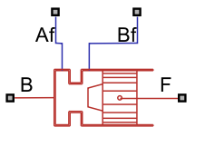
Ports Af and Bf are isothermal liquid conserving
ports associated with the chamber inlet and outlet, respectively. The block cushions
the flow rate from port Bf to port Af. The
check valve in the block is oriented from port Af to port
Bf. Ports B and F
are position-based translational conserving ports. When Modeling
option is Port F connected to piston, port
F is associated with the piston plunger and port
B is associated with the cylinder clamping structure.
When Modeling option is Port B connected to
piston, port F is associated with the
cylinder clamping structure and port B is associated with the
piston plunger.
Ports
Conserving
Parameters
References
[1] Rohner, P. Industrial Hydraulic Control. Fourth edition. Brisbane: John Wiley & Sons, 1995.
Extended Capabilities
Version History
Introduced in R2026a