Heat Exchanger (G-G)
R2026bHeat exchanger for systems with two gas flows
Heat Exchanger (G-G) block
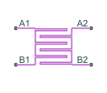
To add a block to a model, double-click the canvas and start typing the block name. Then, select the block from the list.
Libraries:
Simscape /
Fluids /
Heat Exchangers /
Gas
Description
The Heat Exchanger (G-G) block models a gas-gas heat exchanger. The wall can store heat in its bounds, adding to the heat transfer a slight transient delay that scales in proportion to its thermal mass. The fluids are single phase and each is a gas. Neither fluid can switch phase and so, as latent heat is never released, the exchange is strictly one of sensible heat.
Heat Transfer Model
The block heat transfer model derives from the Effectiveness-NTU method. Heat transfer in the steady state then proceeds at a fraction of the ideal rate which the flows, if kept each at its inlet temperature, and if cleared of every thermal resistance in between, could in theory support:
where Q the actual heat transfer rate, QMax is the ideal heat transfer rate, and ε is the fraction of the ideal rate actually observed in a real heat exchanger encumbered with losses. The fraction is the heat exchanger effectiveness, and it is a function of the number of transfer units, or NTU, a measure of the ease with which heat moves between flows, relative to the ease with which the flows absorb that heat:
where the fraction is the overall thermal conductance between the flows and CMin is the smallest of the heat capacity rates from among the flows that belonging to the flow least capable of absorbing heat. The heat capacity rate of a flow depends on the specific heat of the fluid (cp) and on its mass flow rate through the exchanger ():
The effectiveness depends also on the relative disposition of the flows, the number of passes between them, and the mixing condition for each. This dependence reflects in the effectiveness expression used, with different flow arrangements corresponding to different expressions. For a list of the effectiveness expressions, see the E-NTU Heat Transfer block.
The fluid properties that the block uses in heat transfer calculations are the average between the value at the inlet and the value in the fluid volume.
Flow Arrangement
Use the Flow arrangement block parameter to set how the flows meet in the heat exchanger. The flows can run parallel to each other, counter to each other, or across each other. They can also run in a pressurized shell, one through tubes enclosed in the shell, the other around those same tubes. The figure shows an example. The tube flow can make one pass through the shell flow (shown right) or, for greater exchanger effectiveness, multiple passes (left).
Other flow arrangements are possible through a generic parameterization based on tabulated effectiveness data and requiring little detail about the heat exchanger. Flow arrangement, mixing condition, and number of shell or tube passes, if relevant to the heat exchanger, are assumed to manifest in the tabulated data.
Mixing Condition
Use the Cross flow type parameter to mix each of the flows, one of the flows, or none of the flows. Mixing in this context is the lateral movement of fluid in channels that have no internal barriers, normally guides, baffles, fins, or walls. Such movement serves to even out temperature variations in the transverse plane. Mixed flows have variable temperature in the longitudinal plane alone. Unmixed flows have variable temperature in both the transverse and longitudinal planes. The figure shows a mixed flow (i) and an unmixed flow (ii).
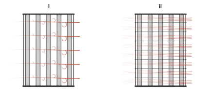
The distinction between mixed and unmixed flows is considered only in cross flow arrangements. There, longitudinal temperature variation in one fluid produces transverse temperature variation in the second fluid that mixing can even out. In counter and parallel flow arrangements, longitudinal temperature variation in one fluid produces longitudinal temperature variation in the second fluid and mixing, as it is of little effect here, is ignored.
Effectiveness Curves
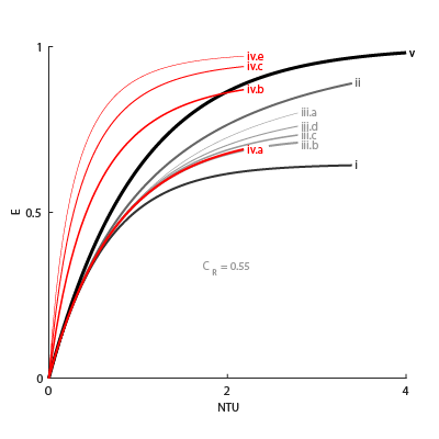
Shell-and-tube exchangers with multiple passes (iv.b-e in the figure for 2, 3, and 4 passes) are most effective. Of exchangers with a single pass, those with counter flows (ii are most effective and those with parallel flows (i) are least.
Cross-flow exchangers are intermediate in effectiveness, with mixing condition playing a factor. They are most effective when both flows are unmixed (iii.a) and least effective when both flows are mixed (iii.b). Mixing just the flow with the smallest heat capacity rate (iii.c) lowers the effectiveness more than mixing just the flow with the largest heat capacity rate (iii.d).
Thermal Resistance
The overall thermal resistance, R, is the sum of the local resistances lining the heat transfer path. The local resistances arise from convection at the surfaces of the wall, conduction through the wall, and, if the wall sides are fouled, conduction through the layers of fouling. Expressed in order from gas side 1 to gas side 2:
where U is the convective heat transfer coefficient, F is the fouling factor, and A is the heat transfer surface area, each for the flow indicated in the subscript. RW is the thermal resistance of the wall.
The wall thermal resistance and fouling factors are simple constants obtained from block parameters. The heat transfer coefficients are elaborate functions of fluid properties, flow geometry, and wall friction, and derive from standard empirical correlations between Reynolds, Nusselt, and Prandtl numbers. The correlations depend on flow arrangement and mixing condition, and are detailed for each in the E-NTU Heat Transfer block on which the block model is based.
Wall Thermal Mass
If you select Enable wall thermal mass, the block models the heat exchanger wall thermal mass, which introduces a delay in the wall's transient response to changes in temperature or heat flux. If you model thermal mass, the wall stores heat in its bounds. This heat storage slows the transition between steady states so that a thermal perturbation on one side does not immediately manifest on the other side. The lag persists until the heat flow rates from the two sides balance.
If you select Enable wall thermal mass, the wall energy conservation is
where:
Mwall is the value of the Wall mass parameter.
cp,wall is the value of the Wall specific heat parameter.
Twall is the effective wall temperature on each side. The block uses this value to model the transient response. You cannot measure this value.
The heat transfer to each fluid is
where:
Tin is the fluid inlet temperature on each side.
C is the heat capacity rate for each fluid.
The number of heat transfer units between the fluid and the wall on each side is
where A is the wall surface area and U is the heat transfer coefficient.
Composite Structure
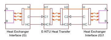
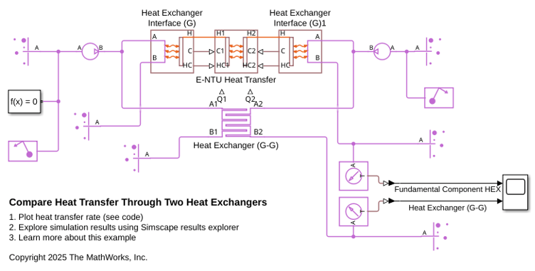
The block is a composite component built from simpler blocks. A Heat Exchanger Interface (G) block models the gas flow on side 1 of the heat exchanger. Another models the gas flow on side 2. An E-NTU Heat Transfer block models the heat exchanged across the wall between the flows.
Examples
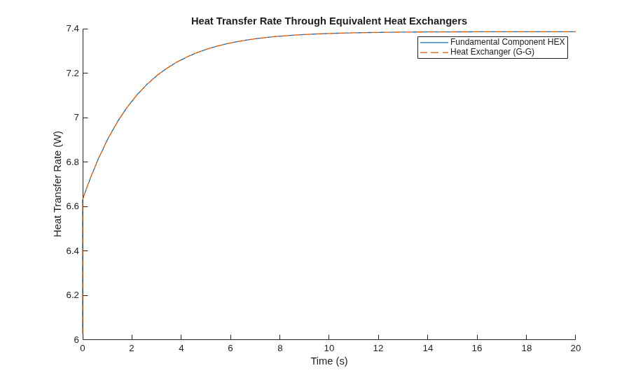
This example compares heat transfer through two equivalent heat exchangers. One heat exchanger uses the Heat Exchanger (G-G) block and the other uses a combination of the E-NTU Heat Transfer and Heat Exchanger Interface (G) blocks.
The Heat Exchanger (G-G) block is a composite component made from two Heat Exchanger Interface (G) blocks and an E-NTU Heat Transfer block. The Heat Exchanger (G-G) block is equivalent to the second heat exchanger in this model, which explicitly uses two Heat Exchanger Interface (G) blocks and an E-NTU Heat Transfer Block.
Because these heat exchangers are equivalent, they have the same characteristics. This figure shows that the rate of heat transfer through both heat exchangers is the same.
Ports
Conserving
Opening for gas 1 to enter and exit its side of the heat exchanger.
Programmatic Use
Port:
A1
Opening for gas 1 to enter and exit its side of the heat exchanger.
Programmatic Use
Port:
B1
Opening for gas 2 to enter and exit its side of the heat exchanger.
Programmatic Use
Port:
A2
Opening for gas 2 to enter and exit its side of the heat exchanger.
Programmatic Use
Port:
B2
Output
Rate of heat transfer to gas 1, in W.
Programmatic Use
Port:
Q1
Rate of heat transfer to gas 2, in W.
Programmatic Use
Port:
Q2
Parameters
Common
Manner in which the flows align in the heat exchanger. The flows can run parallel to each other, counter to each other, or across each other. They can also run in a pressurized shell, one through tubes enclosed in the shell, the other around those tubes. Other flow arrangements are possible through a generic parameterization based on tabulated effectiveness data and requiring little detail about the heat exchanger.
Programmatic Use
| Parameter: | hex_type |
| Values: | "fluids.heat_exchangers.enum.FlowArrangement.ParallelCounter" | "fluids.heat_exchangers.enum.FlowArrangement.ShellTube" | "fluids.heat_exchangers.enum.FlowArrangement.Cross" | "fluids.heat_exchangers.enum.FlowArrangement.Generic" |
Thermal resistance of the interface wall separating the two heat exchanger fluids.
Programmatic Use
Parameter:
R_wall
Number of times the flow traverses the shell before exiting.
Dependencies
To enable this parameter, set Flow
arrangement to Shell and
tube.
Programmatic Use
Parameter:
shell_num
Mixing condition in each of the flow channels. Mixing in this context is the lateral movement of fluid as it proceeds along its flow channel toward the outlet. The flows remain separate from each other. Unmixed flows are common in channels with plates, baffles, or fins. This setting reflects in the effectiveness of the heat exchanger, with unmixed flows being most effective and mixed flows being least.
Dependencies
To enable this parameter, set Flow
arrangement to Shell and
tube.
Programmatic Use
| Parameter: | cross_type |
| Values: | "fluids.heat_exchangers.enum.CrossFlowArrangementGG.MixedMixed" | "fluids.heat_exchangers.enum.CrossFlowArrangementGG.UnmixedUnmixed" | "fluids.heat_exchangers.enum.CrossFlowArrangementGG.MixedUnmixed" | "fluids.heat_exchangers.enum.CrossFlowArrangementGG.UnmixedMixed" |
Number of transfer units at each breakpoint in the lookup table for
the heat exchanger effectiveness number. The table is two-way, with both
the number of transfer units and the thermal capacity ratio serving as
independent coordinates. The block inter- and extrapolates the
breakpoints to obtain the effectiveness at any number of transfer units.
Interpolation is the MATLAB linear type and
extrapolation is nearest.
The numbers specified must be greater than zero and increase monotonically from left to right. The size of the vector must equal the number of rows in the Effectiveness table parameter. If the table has m rows and n columns, the vector for the number of transfer units must be m elements long.
Dependencies
To enable this parameter, set Flow
arrangement to Generic - effectiveness
table.
Programmatic Use
Parameter:
NTU_TLU
Thermal capacity ratio at each breakpoint in lookup table for heat
exchanger effectiveness. The table is two-way, with both the number of
transfer units and the heat capacity rate ratio serving as independent
coordinates. The block inter- and extrapolates the breakpoints to obtain
the effectiveness at any thermal capacity ratio. Interpolation is the
MATLAB linear type and extrapolation is
nearest.
The thermal capacity ratios must be greater than zero and increase monotonically from left to right. The size of the vector must equal the number of columns in the Nusselt number table parameter. If the table has m rows and n columns, the vector for the thermal capacity ratio must be n elements long. The thermal capacity ratio is the fraction of minimum over maximum heat capacity rates.
Dependencies
To enable this parameter, set Flow
arrangement to Generic - effectiveness
table.
Programmatic Use
Parameter:
CR_TLU
Heat exchanger effectiveness at each breakpoint in its lookup table
over the number of transfer units and thermal capacity ratio. The block
inter- and extrapolates the breakpoints to obtain the effectiveness at
any pair of number of transfer units and thermal capacity ratio.
Interpolation is the MATLAB linear type and
extrapolation is nearest.
The effectiveness values must be not be negative. They must align from top to bottom in order of increasing number of transfer units and from left to right in order of increasing thermal capacity ratio. The number of rows must equal the size of the Number of heat transfer units vector parameter, and the number of columns must equal the size of the Thermal capacity ratio vector parameter.
Dependencies
To enable this parameter, set Flow
arrangement to Generic - effectiveness
table.
Programmatic Use
Parameter:
eff_TLU
Whether to model the heat exchanger wall thermal mass. Modeling the wall thermal mass introduces a delay in the transient response of the wall to changes in temperature or heat flux. If you clear Enable wall thermal mass, the block assumes that the wall is thin enough for the transient response to be instantaneous on the time scale of the heat transfer.
Programmatic Use
| Parameter: | wall_thermal_mass |
| Values: | "true" | "false" |
Mass of the heat exchanger wall. The block uses this value to calculate the wall thermal mass.
Dependencies
To enable this parameter, select Enable wall thermal mass.
Programmatic Use
Parameter:
mass_wall
Specific heat of the heat exchanger wall. The block uses this value to calculate the wall thermal mass.
Dependencies
To enable this parameter, select Enable wall thermal mass.
Programmatic Use
Parameter:
cp_wall
Gas 1
Smallest total cross-sectional flow area between inlet and outlet. If the channel is a collection of ducts, tubes, slots, or grooves, the value of this parameter is the sum of the smallest areas at the minimum flow area point. This parameter is the area where the fluid velocity is highest. For example, if the fluid flows perpendicular to a bank of tubes, the value of this parameter is the sum of the gaps between the tubes in one cross-section where the sum of the gaps is smallest is smallest.
Programmatic Use
Parameter:
min_flow_area_1
Total volume of fluid contained in the gas 1 flow channel.
Programmatic Use
Parameter:
gas_volume_1
Effective inner diameter of the flow at its narrowest point. For channels not circular in cross section, that diameter is of an imaginary circle equal in area to the flow cross section. Its value is the ratio of the minimum free-flow area to a fourth of its gross perimeter.
If the channel is a collection of ducts, tubes, slots, or grooves, the gross perimeter is the sum of the perimeters in the collection. If the channel is a single pipe or tube and it is circular in cross section, the hydraulic diameter is the same as the true diameter.
Programmatic Use
Parameter:
Dh_press_1
Start of transition between laminar and turbulent zones. Above this number, inertial forces take hold and the flow grows progressively turbulent. The default value is characteristic of circular pipes and tubes with smooth surfaces.
Programmatic Use
Parameter:
Re_lam_1
End of transition between laminar and turbulent zones. Below this number, viscous forces take hold and the flow grows progressively laminar. The default value is characteristic of circular pipes and tubes with smooth surfaces.
Programmatic Use
Parameter:
Re_tur_1
Mathematical model for pressure loss by viscous friction. This setting determines which expressions to use for calculation and which block parameters to specify as input. See the Heat Exchanger Interface (G) block for the calculations by parameterization.
Programmatic Use
| Parameter: | pressure_loss_spec_1 |
| Values: | "fluids.heat_exchangers.enum.PressureLossSpec.LossCoeff" | "fluids.heat_exchangers.enum.PressureLossSpec.Haaland" | "fluids.heat_exchangers.enum.PressureLossSpec.TabulatedDarcy" | "fluids.heat_exchangers.enum.PressureLossSpec.TabulatedEuler" |
Aggregate loss coefficient for all flow resistances in the flow channel including the wall friction responsible for major loss and the local resistances, due to bends, elbows, and other geometry changes, responsible for minor loss.
The loss coefficient is an empirical dimensionless number commonly used to express the pressure loss due to viscous friction. It can be calculated from experimental data or, in some cases, obtained from product data sheets.
Dependencies
To enable this parameter, set Pressure loss
model to Pressure loss
coefficient.
Programmatic Use
Parameter:
pressure_loss_coeff_1
Total distance the flow must travel to reach across the ports. In multi-pass shell-and-tube exchangers, the total distance is the sum over all shell passes. In tube bundles, corrugated plates, and other channels in which the flow is split into parallel branches, it is the distance covered in a single branch. The longer the flow path, the steeper the major pressure loss due to viscous friction at the wall.
Dependencies
To enable this parameter, set Pressure loss
model to Correlation for flow inside
tubes and Tabulated data - Darcy
friction factor vs Reynolds number.
Programmatic Use
Parameter:
length_press_1
Aggregate minor pressure loss expressed as a length. This length is that which all local resistances, such as elbows, tees, and unions, would add to the flow path if in their place was a simple wall extension. The larger the equivalent length, the steeper the minor pressure loss due to the local resistances.
Dependencies
To enable this parameter, set Pressure loss
model to Correlation for flow inside
tubes.
Programmatic Use
Parameter:
length_add_1
Mean height of the surface protrusions from which wall friction arises. Higher protrusions mean a rougher wall for more friction and so a steeper pressure loss. Surface roughness features in the Haaland correlation from which the Darcy friction factor derives and on which the pressure loss calculation depends.
Dependencies
To enable this parameter, set Pressure loss
model to Correlation for flow inside
tubes.
Programmatic Use
Parameter:
roughness_1
Pressure loss correction for flow cross section in laminar flow conditions. This parameter is commonly referred to as the shape factor. Its ratio to the Reynolds number gives the Darcy friction factor for the pressure loss calculation in the laminar zone. The default value belongs to cylindrical pipes and tubes.
The shape factor derives for certain shapes from the solution of the
Navier-Stokes equations. A square duct has a shape factor of
56, a rectangular duct with aspect ratio of 2:1
has a shape factor of 62, and an annular tube has a
shape factor of 96, as does a slender conduit between
parallel plates.
Dependencies
To enable this parameter, set Pressure loss
model to Correlation for flow inside
tubes.
Programmatic Use
Parameter:
shape_factor_1
Reynolds number at each breakpoint in the lookup table for the Darcy
friction factor. The block inter- and extrapolates the breakpoints to
obtain the Darcy friction factor at any Reynolds number. Interpolation
is the MATLAB linear type and extrapolation is
nearest.
The Reynolds numbers must be greater than zero and increase monotonically from left to right. They can span across laminar, transient, and turbulent zones. Their number must equal the size of the Darcy friction factor vector parameter, with which they are to combine to complete the tabulated breakpoints.
Dependencies
To enable this parameter, set Pressure loss
model to Tabulated data - Darcy friction
factor vs. Reynolds number.
Programmatic Use
Parameter:
Re_friction_TLU_1
Darcy friction factor at each breakpoint in its lookup table over the
Reynolds number. The block inter- and extrapolates the breakpoints to
obtain the Darcy friction factor at any Reynolds number. Interpolation
is the MATLAB linear type and extrapolation is
nearest.
The Darcy friction factors must not be negative and they must align from left to right in order of increasing Reynolds number. Their number must equal the size of the Reynolds number vector for Darcy friction factor parameter, with which they are to combine to complete the tabulated breakpoints.
Dependencies
To enable this parameter, set Pressure loss
model to Tabulated data - Darcy friction
factor vs. Reynolds number.
Programmatic Use
Parameter:
friction_factor_TLU_1
Reynolds number at each breakpoint in the lookup table for the Euler
number. The block inter- and extrapolates the breakpoints to obtain the
Euler number at any Reynolds number. Interpolation is the MATLAB
linear type and extrapolation is
nearest.
The Reynolds numbers must be greater than zero and increase monotonically from left to right. They can span across laminar, transient, and turbulent zones. Their number must equal the size of the Euler number vector parameter, with which they are to combine to complete the tabulated breakpoints.
Dependencies
To enable this parameter, set Pressure loss
model to Tabulated data - Euler number
vs. Reynolds number.
Programmatic Use
Parameter:
Re_Euler_TLU_1
Euler number at each breakpoint in its lookup table over the Reynolds
number. The block inter- and extrapolates the breakpoints to obtain the
Euler number at any Reynolds number. Interpolation is the MATLAB
linear type and extrapolation is
nearest.
The Euler numbers must not be negative and they must align from left to right in order of increasing Reynolds number. Their number must equal the size of the Reynolds number vector for Euler number parameter, with which they are to combine to complete the tabulated breakpoints.
Dependencies
To enable this parameter, set Pressure loss
model to Tabulated data - Euler number
vs. Reynolds number.
Programmatic Use
Parameter:
Euler_TLU_1
Mathematical model for heat transfer between fluid and wall. The choice of model determines which expressions to apply and which parameters to specify for heat transfer calculation. See the E-NTU Heat Transfer block for the calculations by parameterization.
Programmatic Use
| Parameter: | heat_transfer_spec_1 |
| Values: | "fluids.heat_exchangers.enum.HeatCoeffSpec.Constant" | "fluids.heat_exchangers.enum.HeatCoeffSpec.Gneilinski" | "fluids.heat_exchangers.enum.HeatCoeffSpec.TabulatedColburn" | "fluids.heat_exchangers.enum.HeatCoeffSpec.TabulatedNusselt" |
Effective surface area used in heat transfer between fluid and wall. The effective surface area is the sum of primary and secondary surface areas, or those of the wall, where it is exposed to fluid, and of the fins, if any are used. Fin surface area is normally scaled by a fin efficiency factor.
Programmatic Use
Parameter:
heat_transfer_area_1
Heat transfer coefficient for convection between fluid and wall. Resistance due to fouling is captured separately in the Fouling factor parameter.
Dependencies
To enable this parameter, set Heat transfer coefficient
model to Constant heat transfer
coefficient.
Programmatic Use
Parameter:
heat_coeff_1
Length of the pipe or channel from inlet to outlet.
Dependencies
To enable this parameter, set Heat transfer coefficient
model to Tabulated data - Colburn factor
vs. Reynolds number or Tabulated data
- Nusselt number vs. Reynolds number and Prandtl
number.
Programmatic Use
Parameter:
length_heat_1
Constant assumed for Nusselt number in laminar flow. The Nusselt number factors in the calculation of the heat transfer coefficient between fluid and wall, on which the heat transfer rate depends. The default value belongs to cylindrical pipes and tubes.
Dependencies
To enable this parameter, set Heat transfer coefficient
model to Correlation for flow inside
tubes.
Programmatic Use
Parameter:
Nu_lam_1
Reynolds number at each breakpoint in the lookup table for the Colburn
factor. The block inter- and extrapolates the breakpoints to obtain the
Colburn factor at any Reynolds number. Interpolation is the MATLAB
linear type and extrapolation is
nearest.
The Reynolds numbers must be greater than zero and increase monotonically from left to right. They can span across laminar, transient, and turbulent zones. Their number must equal the size of the Colburn factor vector parameter, with which they are to combine to complete the tabulated breakpoints.
Dependencies
To enable this parameter, set Heat transfer coefficient
model to Tabulated data - Colburn factor
vs. Reynolds number.
Programmatic Use
Parameter:
Re_Colburn_TLU_1
Colburn factor at each breakpoint in its lookup table over the
Reynolds number. The block inter- and extrapolates the breakpoints to
obtain the Euler number at any Reynolds number. Interpolation is the
MATLAB linear type and extrapolation is
nearest.
The Colburn factors must not be negative and they must align from left to right in order of increasing Reynolds number. Their number must equal the size of the Reynolds number vector for Colburn factor parameter, with which they are to combine to complete the tabulated breakpoints.
Dependencies
To enable this parameter, set Heat transfer coefficient
model to Tabulated data - Colburn factor
vs. Reynolds number.
Programmatic Use
Parameter:
Colburn_factor_TLU_1
Reynolds number at each breakpoint in the lookup table for the Nusselt
number. The table is two-way, with both Reynolds and Prandtl numbers
serving as independent coordinates. The block inter- and extrapolates
the breakpoints to obtain the Nusselt number at any Reynolds number.
Interpolation is the MATLAB linear type and
extrapolation is nearest.
The Reynolds numbers must be greater than zero and increase monotonically from left to right. They can span across laminar, transient, and turbulent zones. The size of the vector must equal the number of rows in the Nusselt number table parameter. If the table has m rows and n columns, the Reynolds number vector must be m elements long.
Dependencies
To enable this parameter, set Heat transfer coefficient
model to Tabulated data - Nusselt number
vs. Reynolds number and Prandtl number.
Programmatic Use
Parameter:
Re_Nu_TLU_1
Prandtl number at each breakpoint in the lookup table for the Nusselt
number. The table is two-way, with both Reynolds and Prandtl numbers
serving as independent coordinates. The block inter- and extrapolates
the breakpoints to obtain the Nusselt number at any Prandtl number.
Interpolation is the MATLAB linear type and
extrapolation is nearest.
The Prandtl numbers must be greater than zero and increase monotonically from left to right. They can span across laminar, transient, and turbulent zones. The size of the vector must equal the number of columns in the Nusselt number table parameter. If the table has m rows and n columns, the Prandtl number vector must be n elements long.
Dependencies
To enable this parameter, set Heat transfer coefficient
model to Tabulated data - Nusselt number
vs. Reynolds number and Prandtl number.
Programmatic Use
Parameter:
Pr_Nu_TLU_1
Nusselt number at each breakpoint in its lookup table over the
Reynolds and Prandtl numbers. The block inter- and extrapolates the
breakpoints to obtain the Nusselt number at any pair of Reynolds and
Prandtl numbers. Interpolation is the MATLAB linear
type and extrapolation is nearest. By determining the
Nusselt number, the table feeds the calculation from which the heat
transfer coefficient between fluid and wall derives.
The Nusselt numbers must be greater than zero. They must align from top to bottom in order of increasing Reynolds number and from left to right in order of increasing Prandtl numbers. The number of rows must equal the size of the Reynolds number vector for Nusselt number parameter, and the number of columns must equal the size of the Prandtl number vector for Nusselt number parameter.
Dependencies
To enable this parameter, set Heat transfer coefficient
model to Tabulated data - Nusselt number
vs. Reynolds number and Prandtl number.
Measure of thermal resistance due to fouling deposits which over time tend to build on the exposed surfaces of the wall. The deposits, as they impose between the fluid and wall a new solid layer through which heat must traverse, add to the heat transfer path an extra thermal resistance. Fouling deposits grow slowly and the resistance due to them is accordingly assumed constant during simulation.
Programmatic Use
Parameter:
fouling_factor_1
Lower bound for the heat transfer coefficient between fluid and wall. If calculation returns a lower heat transfer coefficient, this bound replaces the calculated value.
Programmatic Use
Parameter:
min_heat_coeff_1
Mass flow rate below which the flow is considered to reverse direction through this fluid path.
Programmatic Use
Parameter:
mdot_threshold_1
Gas 2
Smallest total cross-sectional flow area between inlet and outlet. If the channel is a collection of ducts, tubes, slots, or grooves, the value of this parameter is the sum of the smallest areas at the minimum flow area point. This parameter is the area where the fluid velocity is highest. For example, if the fluid flows perpendicular to a bank of tubes, the value of this parameter is the sum of the gaps between the tubes in one cross-section where the sum of the gaps is smallest is smallest.
Programmatic Use
Parameter:
min_flow_area_2
Total volume of fluid contained in the gas 2 flow channel.
Programmatic Use
Parameter:
gas_volume_2
Effective inner diameter of the flow at its narrowest point. For channels not circular in cross section, that diameter is of an imaginary circle equal in area to the flow cross section. Its value is the ratio of the minimum free-flow area to a fourth of its gross perimeter.
If the channel is a collection of ducts, tubes, slots, or grooves, the gross perimeter is the sum of the perimeters in the collection. If the channel is a single pipe or tube and it is circular in cross section, the hydraulic diameter is the same as the true diameter.
Programmatic Use
Parameter:
Dh_press_2
Start of transition between laminar and turbulent zones. Above this number, inertial forces take hold and the flow grows progressively turbulent. The default value is characteristic of circular pipes and tubes with smooth surfaces.
Programmatic Use
Parameter:
Re_lam_2
End of transition between laminar and turbulent zones. Below this number, viscous forces take hold and the flow grows progressively laminar. The default value is characteristic of circular pipes and tubes with smooth surfaces.
Programmatic Use
Parameter:
Re_tur_2
Mathematical model for pressure loss by viscous friction. This setting determines which expressions to use for calculation and which block parameters to specify as input. See the Heat Exchanger Interface (G) block for the calculations by parameterization.
Programmatic Use
| Parameter: | pressure_loss_spec_2 |
| Values: | "fluids.heat_exchangers.enum.PressureLossSpec.LossCoeff" | "fluids.heat_exchangers.enum.PressureLossSpec.Haaland" | "fluids.heat_exchangers.enum.PressureLossSpec.TabulatedDarcy" | "fluids.heat_exchangers.enum.PressureLossSpec.TabulatedEuler" |
Aggregate loss coefficient for all flow resistances in the flow channel including the wall friction responsible for major loss and the local resistances, due to bends, elbows, and other geometry changes, responsible for minor loss.
The loss coefficient is an empirical dimensionless number commonly used to express the pressure loss due to viscous friction. It can be calculated from experimental data or, in some cases, obtained from product data sheets.
Dependencies
To enable this parameter, set Pressure loss
model to Pressure loss
coefficient.
Programmatic Use
Parameter:
pressure_loss_coeff_2
Total distance the flow must travel to reach across the ports. In multi-pass shell-and-tube exchangers, the total distance is the sum over all shell passes. In tube bundles, corrugated plates, and other channels in which the flow is split into parallel branches, it is the distance covered in a single branch. The longer the flow path, the steeper the major pressure loss due to viscous friction at the wall.
Dependencies
To enable this parameter, set Pressure loss
model to Correlation for flow inside
tubes and Tabulated data - Darcy
friction factor vs Reynolds number.
Programmatic Use
Parameter:
length_press_2
Aggregate minor pressure loss expressed as a length. This length is that which all local resistances, such as elbows, tees, and unions, would add to the flow path if in their place was a simple wall extension. The larger the equivalent length, the steeper the minor pressure loss due to the local resistances.
Dependencies
To enable this parameter, set Pressure loss
model to Correlation for flow inside
tubes.
Programmatic Use
Parameter:
length_add_2
Mean height of the surface protrusions from which wall friction arises. Higher protrusions mean a rougher wall for more friction and so a steeper pressure loss. Surface roughness features in the Haaland correlation from which the Darcy friction factor derives and on which the pressure loss calculation depends.
Dependencies
To enable this parameter, set Pressure loss
model to Correlation for flow inside
tubes.
Programmatic Use
Parameter:
roughness_2
Pressure loss correction for flow cross section in laminar flow conditions. This parameter is commonly referred to as the shape factor. Its ratio to the Reynolds number gives the Darcy friction factor for the pressure loss calculation in the laminar zone. The default value belongs to cylindrical pipes and tubes.
The shape factor derives for certain shapes from the solution of the
Navier-Stokes equations. A square duct has a shape factor of
56, a rectangular duct with aspect ratio of 2:1
has a shape factor of 62, and an annular tube has a
shape factor of 96, as does a slender conduit between
parallel plates.
Dependencies
To enable this parameter, set Pressure loss
model to Correlation for flow inside
tubes.
Programmatic Use
Parameter:
shape_factor_2
Reynolds number at each breakpoint in the lookup table for the Darcy
friction factor. The block inter- and extrapolates the breakpoints to
obtain the Darcy friction factor at any Reynolds number. Interpolation
is the MATLAB linear type and extrapolation is
nearest.
The Reynolds numbers must be greater than zero and increase monotonically from left to right. They can span across laminar, transient, and turbulent zones. Their number must equal the size of the Darcy friction factor vector parameter, with which they are to combine to complete the tabulated breakpoints.
Dependencies
To enable this parameter, set Pressure loss
model to Tabulated data - Darcy friction
factor vs. Reynolds number.
Programmatic Use
Parameter:
Re_friction_TLU_2
Darcy friction factor at each breakpoint in its lookup table over the
Reynolds number. The block inter- and extrapolates the breakpoints to
obtain the Darcy friction factor at any Reynolds number. Interpolation
is the MATLAB linear type and extrapolation is
nearest.
The Darcy friction factors must not be negative and they must align from left to right in order of increasing Reynolds number. Their number must equal the size of the Reynolds number vector for Darcy friction factor parameter, with which they are to combine to complete the tabulated breakpoints.
Dependencies
To enable this parameter, set Pressure loss
model to Tabulated data - Darcy friction
factor vs. Reynolds number.
Programmatic Use
Parameter:
friction_factor_TLU_2
Reynolds number at each breakpoint in the lookup table for the Euler
number. The block inter- and extrapolates the breakpoints to obtain the
Euler number at any Reynolds number. Interpolation is the MATLAB
linear type and extrapolation is
nearest.
The Reynolds numbers must be greater than zero and increase monotonically from left to right. They can span across laminar, transient, and turbulent zones. Their number must equal the size of the Euler number vector parameter, with which they are to combine to complete the tabulated breakpoints.
Dependencies
To enable this parameter, set Pressure loss
model to Tabulated data - Euler number
vs. Reynolds number.
Programmatic Use
Parameter:
Re_Euler_TLU_2
Euler number at each breakpoint in its lookup table over the Reynolds
number. The block inter- and extrapolates the breakpoints to obtain the
Euler number at any Reynolds number. Interpolation is the MATLAB
linear type and extrapolation is
nearest.
The Euler numbers must not be negative and they must align from left to right in order of increasing Reynolds number. Their number must equal the size of the Reynolds number vector for Euler number parameter, with which they are to combine to complete the tabulated breakpoints.
Dependencies
To enable this parameter, set Pressure loss
model to Tabulated data - Euler number
vs. Reynolds number.
Programmatic Use
Parameter:
Euler_TLU_2
Mathematical model for heat transfer between fluid and wall. The choice of model determines which expressions to apply and which parameters to specify for heat transfer calculation. See the E-NTU Heat Transfer block for the calculations by parameterization.
Programmatic Use
| Parameter: | heat_transfer_spec_2 |
| Values: | "fluids.heat_exchangers.enum.HeatCoeffSpec.Constant" | "fluids.heat_exchangers.enum.HeatCoeffSpec.Gneilinski" | "fluids.heat_exchangers.enum.HeatCoeffSpec.TabulatedColburn" | "fluids.heat_exchangers.enum.HeatCoeffSpec.TabulatedNusselt" |
Effective surface area used in heat transfer between fluid and wall. The effective surface area is the sum of primary and secondary surface areas, or those of the wall, where it is exposed to fluid, and of the fins, if any are used. Fin surface area is normally scaled by a fin efficiency factor.
Programmatic Use
Parameter:
heat_transfer_area_2
Heat transfer coefficient for convection between fluid and wall. Resistance due to fouling is captured separately in the Fouling factor parameter.
Dependencies
To enable this parameter, set Heat transfer coefficient
model to Constant heat transfer
coefficient.
Programmatic Use
Parameter:
heat_coeff_2
Length of the pipe or channel from inlet to outlet.
Dependencies
To enable this parameter, set Heat transfer coefficient
model to Tabulated data - Colburn factor
vs. Reynolds number or Tabulated data
- Nusselt number vs. Reynolds number and Prandtl
number.
Programmatic Use
Parameter:
length_heat_2
Constant assumed for Nusselt number in laminar flow. The Nusselt number factors in the calculation of the heat transfer coefficient between fluid and wall, on which the heat transfer rate depends. The default value belongs to cylindrical pipes and tubes.
Dependencies
To enable this parameter, set Heat transfer coefficient
model to Correlation for flow inside
tubes.
Programmatic Use
Parameter:
Nu_lam_2
Reynolds number at each breakpoint in the lookup table for the Colburn
factor. The block inter- and extrapolates the breakpoints to obtain the
Colburn factor at any Reynolds number. Interpolation is the MATLAB
linear type and extrapolation is
nearest.
The Reynolds numbers must be greater than zero and increase monotonically from left to right. They can span across laminar, transient, and turbulent zones. Their number must equal the size of the Colburn factor vector parameter, with which they are to combine to complete the tabulated breakpoints.
Dependencies
To enable this parameter, set Heat transfer coefficient
model to Tabulated data - Colburn factor
vs. Reynolds number.
Programmatic Use
Parameter:
Re_Colburn_TLU_2
Colburn factor at each breakpoint in its lookup table over the
Reynolds number. The block inter- and extrapolates the breakpoints to
obtain the Euler number at any Reynolds number. Interpolation is the
MATLAB linear type and extrapolation is
nearest.
The Colburn factors must not be negative and they must align from left to right in order of increasing Reynolds number. Their number must equal the size of the Reynolds number vector for Colburn factor parameter, with which they are to combine to complete the tabulated breakpoints.
Dependencies
To enable this parameter, set Heat transfer coefficient
model to Tabulated data - Colburn factor
vs. Reynolds number.
Programmatic Use
Parameter:
Colburn_factor_TLU_2
Reynolds number at each breakpoint in the lookup table for the Nusselt
number. The table is two-way, with both Reynolds and Prandtl numbers
serving as independent coordinates. The block inter- and extrapolates
the breakpoints to obtain the Nusselt number at any Reynolds number.
Interpolation is the MATLAB linear type and
extrapolation is nearest.
The Reynolds numbers must be greater than zero and increase monotonically from left to right. They can span across laminar, transient, and turbulent zones. The size of the vector must equal the number of rows in the Nusselt number table parameter. If the table has m rows and n columns, the Reynolds number vector must be m elements long.
Dependencies
To enable this parameter, set Heat transfer coefficient
model to Tabulated data - Nusselt number
vs. Reynolds number and Prandtl number.
Programmatic Use
Parameter:
Re_Nu_TLU_2
Prandtl number at each breakpoint in the lookup table for the Nusselt
number. The table is two-way, with both Reynolds and Prandtl numbers
serving as independent coordinates. The block inter- and extrapolates
the breakpoints to obtain the Nusselt number at any Prandtl number.
Interpolation is the MATLAB linear type and
extrapolation is nearest.
The Prandtl numbers must be greater than zero and increase monotonically from left to right. They can span across laminar, transient, and turbulent zones. The size of the vector must equal the number of columns in the Nusselt number table parameter. If the table has m rows and n columns, the Prandtl number vector must be n elements long.
Dependencies
To enable this parameter, set Heat transfer coefficient
model to Tabulated data - Nusselt number
vs. Reynolds number and Prandtl number.
Programmatic Use
Parameter:
Pr_Nu_TLU_2
Nusselt number at each breakpoint in its lookup table over the
Reynolds and Prandtl numbers. The block inter- and extrapolates the
breakpoints to obtain the Nusselt number at any pair of Reynolds and
Prandtl numbers. Interpolation is the MATLAB linear
type and extrapolation is nearest. By determining the
Nusselt number, the table feeds the calculation from which the heat
transfer coefficient between fluid and wall derives.
The Nusselt numbers must be greater than zero. They must align from top to bottom in order of increasing Reynolds number and from left to right in order of increasing Prandtl numbers. The number of rows must equal the size of the Reynolds number vector for Nusselt number parameter, and the number of columns must equal the size of the Prandtl number vector for Nusselt number parameter.
Dependencies
To enable this parameter, set Heat transfer coefficient
model to Tabulated data - Nusselt number
vs. Reynolds number and Prandtl number.
Measure of thermal resistance due to fouling deposits which over time tend to build on the exposed surfaces of the wall. The deposits, as they impose between the fluid and wall a new solid layer through which heat must traverse, add to the heat transfer path an extra thermal resistance. Fouling deposits grow slowly and the resistance due to them is accordingly assumed constant during simulation.
Programmatic Use
Parameter:
fouling_factor_2
Lower bound for the heat transfer coefficient between fluid and wall. If calculation returns a lower heat transfer coefficient, this bound replaces the calculated value.
Programmatic Use
Parameter:
min_heat_coeff_2
Mass flow rate below which the flow is considered to reverse direction through this fluid path.
Programmatic Use
Parameter:
mdot_threshold_2
Effects and Initial Conditions
Option to model the pressure dynamics in the gas channel. If you clear this checkbox, the block removes the pressure derivative terms from the component energy and mass conservation equations.
Programmatic Use
| Parameter: | dynamic_compressibility_1 |
| Values: | "true" | "false" |
Gas temperature at nominal operating conditions. The block uses this value to calculate the nominal density to use in the mass and energy conservation equation when dynamic compressibility is disabled.
Dependencies
To enable this parameter, clear the Enable Gas 1 dynamic compressibility checkbox.
Programmatic Use
Parameter:
T_nominal_1
Gas pressure at nominal operating conditions. The block uses this value to calculate the nominal density to use in the mass and energy conservation equation when dynamic compressibility is disabled.
Dependencies
To enable this parameter, clear the Enable Gas 1 dynamic compressibility checkbox.
Programmatic Use
Parameter:
p_nominal_1
Temperature in the gas channel at the start of simulation
Programmatic Use
Parameter:
T0_1
Pressure in the gas channel at the start of simulation.
Dependencies
To enable this parameter, select Enable Gas 1 dynamic compressibility.
Programmatic Use
Parameter:
p0_1
Option to model the pressure dynamics in the gas channel. If you clear this checkbox, the block removes the pressure derivative terms from the component energy and mass conservation equations.
Programmatic Use
| Parameter: | dynamic_compressibility_2 |
| Values: | "true" | "false" |
Gas temperature at nominal operating conditions. The block uses this value to calculate the nominal density to use in the mass and energy conservation equation when dynamic compressibility is disabled.
Dependencies
To enable this parameter, clear the Enable Gas 2 dynamic compressibility checkbox.
Programmatic Use
Parameter:
T_nominal_2
Gas pressure at nominal operating conditions. The block uses this value to calculate the nominal density to use in the mass and energy conservation equation when dynamic compressibility is disabled.
Dependencies
To enable this parameter, clear the Enable Gas 2 dynamic compressibility checkbox.
Programmatic Use
Parameter:
p_nominal_2
Temperature in the gas 2 channel at the start of simulation.
Programmatic Use
Parameter:
T0_2
Pressure in the gas 2 channel at the start of simulation.
Dependencies
To enable this parameter, select Enable Gas 2 dynamic compressibility.
Programmatic Use
Parameter:
p0_2
Extended Capabilities
C/C++ Code Generation
Generate C and C++ code using Simulink® Coder™.
Version History
Introduced in R2017bUse ports Q1 and Q2 to output the rate of heat transfer to gas 1 and gas 2, respectively.
The Heat Exchanger (G-G) block can now optionally model dynamic compressibility by using the Enable dynamic compressibility parameter. Previously, this block always modeled pressure dynamics, which can cause models to take longer to achieve steady state. Clear the Enable dynamic compressibility parameter to prevent dynamic compressibility modeling.
The Modeling option parameter has been removed, and the
modeling options are now two separate blocks. The Heat Exchanger
(G-G) block uses the heat transfer model that was previously used when
Modeling option was E-NTU Model.
To use the block model used when Modeling option was
Simple model, see the Specific
Dissipation Heat Exchanger (G-G) block.
MATLAB Command
You clicked a link that corresponds to this MATLAB command:
Run the command by entering it in the MATLAB Command Window. Web browsers do not support MATLAB commands.


选择网站
选择网站以获取翻译的可用内容,以及查看当地活动和优惠。根据您的位置,我们建议您选择:。
您也可以从以下列表中选择网站:
如何获得最佳网站性能
选择中国网站(中文或英文)以获得最佳网站性能。其他 MathWorks 国家/地区网站并未针对您所在位置的访问进行优化。
美洲
- América Latina (Español)
- Canada (English)
- United States (English)
欧洲
- Belgium (English)
- Denmark (English)
- Deutschland (Deutsch)
- España (Español)
- Finland (English)
- France (Français)
- Ireland (English)
- Italia (Italiano)
- Luxembourg (English)
- Netherlands (English)
- Norway (English)
- Österreich (Deutsch)
- Portugal (English)
- Sweden (English)
- Switzerland
- United Kingdom (English)