3-Position Valve Actuator
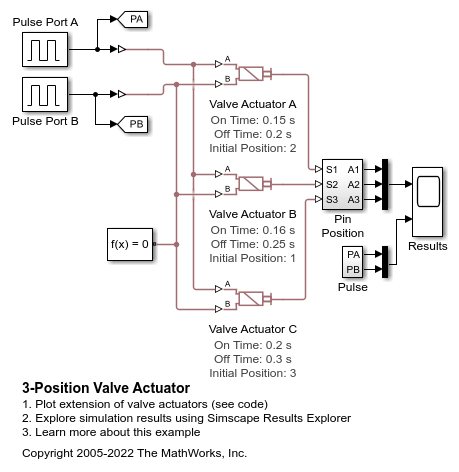
This example shows the behavior of three different Multiposition Valve Actuator blocks. In each block Actuator positions is 3. All three actuators are driven by the same pulse signals. The values of the Push-pin stroke, Switching-on time and Switching-off time parameters of the three actuators are different, which illustrates the parameter impact.
Model
Simulation Results from Scopes
These plots show the behaviors of the three valve actuators. A pulse first applies to port A, and after 1 second, another pulse applies to port B. The Valve Actuators A, B, and C start from the Extended positive, Neutral, and Extended negative positions, respectively. As a result, Actuators A and C return to the neutral position in the initial period before the first pulse applies. Each actuator position reaches the push-pin stroke in the positive direction when the first pulse applies, and the duration of each extension is the specified switching-on time. When the first signal reduces to zero, the positions decrease over the specified switching-off times. When the second pulse applies, the positions reach the push-pin strokes in the negative direction and then return to zero, within the switching-on and the switching-off times, respectively.
