Electric Vehicle Thermal Management with Heat Pump
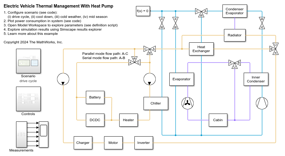
This example models the thermal management system of a battery electric vehicle (BEV) that includes a heat pump for cabin heating. The system consists of two liquid coolant loops, a refrigerant loop, and a cabin air HVAC loop. The thermal loads are the batteries, the power electronics, and the cabin.
You can join the two coolant loops together in serial mode or keep them separate in parallel mode using the two parallel-serial mode directional valves. In cold temperatures, the coolant loops operate in serial mode so that heat from the motor warms the batteries. If necessary, a heater can provide additional heat. In moderate temperatures, the coolant loops remain in serial mode and the radiator cools both the batteries and the power electronics. If the environment temperature or coolant temperature rises above 35 degC, the coolant loops switch to parallel mode and separate. One loop cools the power electronics using the radiator. The other loop cools the batteries by using the chiller in the refrigerant loop.
The refrigerant loop provides cooling to the cabin and batteries in cold loop mode or heating to the cabin in heat pump mode. It consists of a compressor, an inner condenser, a condenser evaporator, a chiller, an evaporator, a heat exchanger, and three expansion valves. In cold loop mode, cabin air bypasses the inner condenser and the heat pump expansion valve remains fully open. Therefore, the condenser evaporator acts as a condenser to reject heat to the environment. The chiller expansion valve meters refrigerant to the chiller to cool the coolant. The evaporator expansion valve meters refrigerant to the evaporator to cool and dehumidify the cabin air.
In heat pump mode, the inner condenser heats the cabin air. The heat pump expansion valve meters refrigerant to the condenser evaporator, which acts as an evaporator to absorb heat from the environment. The chiller evaporator bypass valve directs refrigerant to the heat exchanger instead of the chiller and the evaporator to absorb heat from the coolant before returning to the accumulator and compressor. This flow path allows the system to reuse some of the waste heat from the batteries and power electronics, which improves the heat pump mode cycle efficiency by reducing the pressure difference that the compressor needs to maintain.
The cabin air HVAC loop consists of a blower, an evaporator, a blend door, an inner condenser, and the vehicle cabin. The evaporator provides air conditioning in hot weather and the inner condenser provides heat in cold weather. The blend door directs air to the inner condenser in heat pump mode and bypasses it in cold loop mode. The blower maintains the cabin temperature at a controlled setpoint.
The model has four possible scenarios:
The drive cycle scenario simulates driving conditions in 30 degC weather with the refrigerant loop in cold loop mode. The vehicle speed is based on the New European Drive Cycle (NEDC) followed by 30 min of high speed to increase the battery heat load. The coolant loop starts off in serial mode but switches to parallel mode when the battery is generating a lot of heat.
The cool down scenario simulates a stationary vehicle in 40 degC weather with the refrigerant loop in cold loop mode.
The cold weather scenario simulates driving conditions in -10 degC weather with the refrigerant loop in heat pump mode.
The mid season scenario simulates driving conditions in 25 degC followed by 5 degC weather. The refrigerant loop starts off in cold loop mode and then switches to heat pump mode.
The total refrigerant charge is the same for each scenario despite the different initial conditions because the model uses the function refrigerantChargeProperties to calculate the initial refrigerant pressure and vapor quality corresponding to the desired charge and environment temperature.
For more information on electric vehicle thermal management with a transcritical CO2 heat pump, see Electric Vehicle Thermal Management With CO2.
For more information on electric vehicle thermal management without a heat pump, see Electric Vehicle Thermal Management.
Model
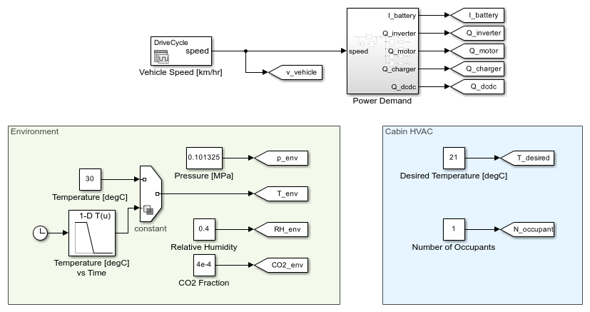
Scenario Subsystem
This subsystem sets up the environment conditions and inputs to the system for the selected scenario. The battery current demand and power electronics heat load are a function of the vehicle speed based on tabulated data.
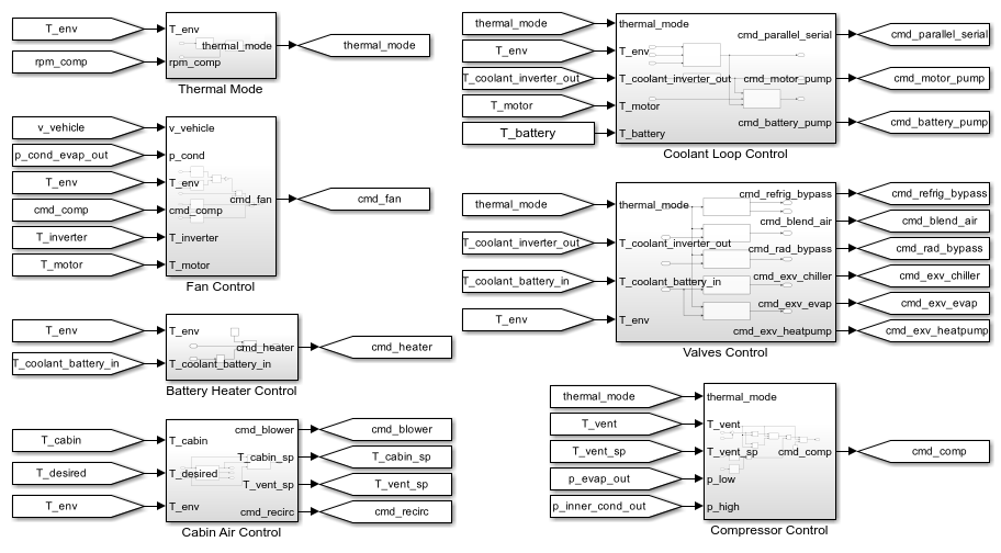
Controls Subsystem
This subsystem consists of all of the controllers for the pumps, compressor, fan, blower, and valves in the thermal management system.
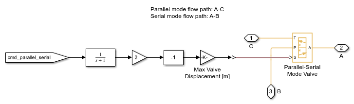
Parallel-Serial Mode Valve 1 Subsystem
There are two identical parallel-serial mode valves that act in unison to control whether the coolant loop operates in parallel mode or serial mode. One of the two valves is shown below. When ports A and C are connected, it is in parallel mode. The two coolant loops are separated with their own coolant tanks and pumps. When ports A and B are connected, it is in serial mode. The two coolant loops are joined together and the two pumps are synchronized to provide the same flow rate.
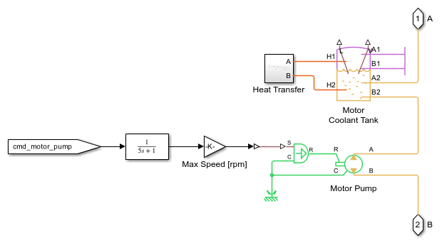
Motor Pump and Battery Pump Subsystems
The motor pump and battery pump subsystems are the same. The motor pump is shown below. The motor pump drives the coolant loop that cools the charger, motor, and inverter. The battery pump drives the coolant loop that cools the batteries and DC-DC converter.
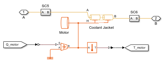
Motor, Charger, Inverter, and DCDC Subsystems
The motor, charger, inverter, and DCDC subsystems are the same. The motor is shown below. Each of the four subsystems models a coolant jacket around the motor, charger, inverter, or DC-DC converter, represented by a heat flow rate source and a thermal mass.
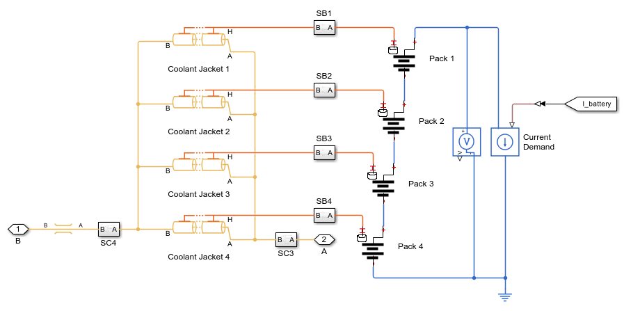
Battery Subsystem
The batteries are modeled as four separate packs surrounded by a coolant jacket. The battery packs generate voltage and heat based on the current demand. The model assumes that the coolant flows in narrow channels around the battery packs.
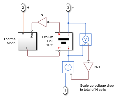
Pack 1 Subsystem
Each battery pack model contains a stack of lithium-ion cells coupled with a thermal model. The power losses in the cells correspond to the generated heat.
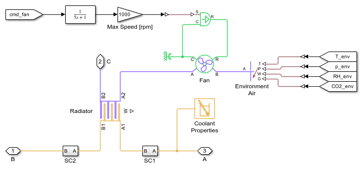
Radiator Subsystem
The radiator is a rectangular tube-and-fin type heat exchanger that dissipates coolant heat to the environment air. The air flow passes through the condenser evaporator before the radiator. The vehicle speed and the fan located behind the radiator drives the air flow.
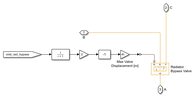
Radiator Bypass Valve Subsystem
In cold loop mode, this 3-way valve directs coolant to the radiator to reject heat. In heat pump mode, this 3-way valve directs coolant to the heat exchanger to transfer waste heat to the refrigerant and reduce the energy consumption of the heat pump. However, if the coolant becomes too hot, the 3-way valve directs coolant back to the radiator to transfer heat directly to the environment.
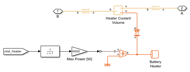
Heater Subsystem
The battery heater model contains a heat flow rate source and a thermal mass. The battery heater turns on in cold weather to bring the battery temperature above 5 degC.
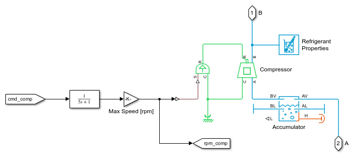
Compressor Subsystem
The compressor drives the flow in the refrigerant loop. It is controlled to maintain a cabin air vent temperature setpoint. The compressor turns off when transitioning between cold loop mode and heat pump mode to allow the system to ramp down before starting the new mode. The accumulator provides storage for the refrigerant and permits only superheated vapor to flow into the compressor.
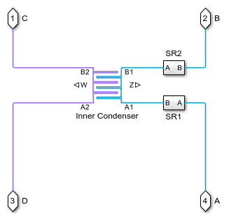
Inner Condenser Subsystem
The inner condenser is a rectangular tube-and-fin type heat exchanger that transfers heat from the refrigerant to the cabin air in heat pump mode. The blend door directs cabin air flow through the inner condenser to absorb heat. In cold loop mode, the blend door directs cabin air to bypass the inner condenser so that no heat transfer occurs.
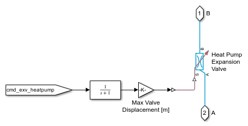
Heat Pump Expansion Valve Subsystem
The heat pump expansion valve provides the pressure drop needed to vaporize the refrigerant entering the condenser evaporator in heat pump mode. It uses a simple open loop control based on the environment temperature. It is fully open in cold loop mode to allow refrigerant to pass through with minimal losses.
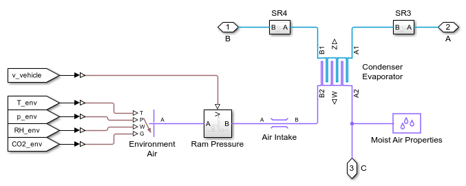
Condenser Evaporator Subsystem
The condenser evaporator is a rectangular tube-and-fin type heat exchanger that either transfers heat from the refrigerant to environment air in cold loop mode or transfers heat from environment air to the refrigerant in heat pump mode. The vehicle speed and the fan located behind the radiator drives the air flow.
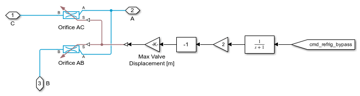
Chiller Evaporator Bypass Valve Subsystem
Two orifices operating in the opposite manner model the 3-way valve. In cold loop mode, the valve directs refrigerant to the chiller and expansion valve to cool the batteries and cabin. In heat pump mode, the valve directs the refrigerant to the heat exchanger, bypassing the chiller and evaporator.
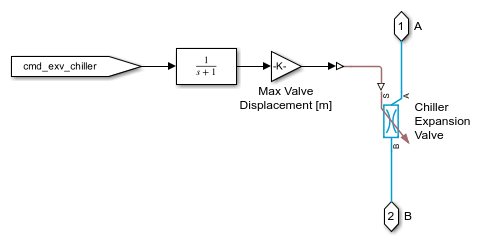
Chiller Expansion Valve Subsystem
The chiller expansion valve provides the pressure drop needed to vaporize the refrigerant entering the chiller in cold loop mode. The temperature of the coolant flowing through the battery packs control the expansion valve.
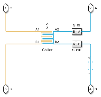
Chiller Subsystem
The chiller is a shell-and-tube type heat exchanger that transfers heat from the coolant to the refrigerant.
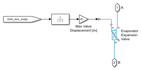
Evaporator Expansion Valve Subsystem
The evaporator expansion valve provides the pressure drop needed to vaporize the refrigerant entering the evaporator in cold loop mode. It uses a simple open loop control based on the environment temperature.
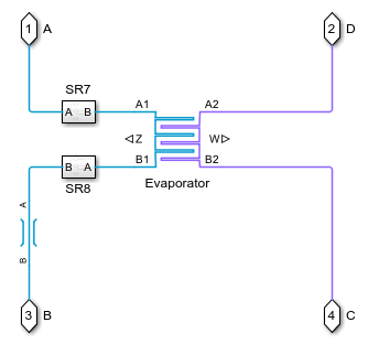
Evaporator Subsystem
The evaporator is a rectangular tube-and-fin type heat exchanger that transfers heat from the cabin air to the refrigerant. It also dehumidifies the air when the air is humid.
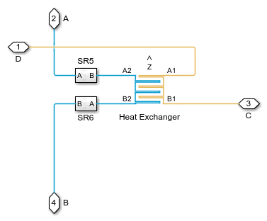
Heat Exchanger Subsystem
The heat exchanger is a tube bank heat exchanger that transfers heat from the coolant to the refrigerant. Its purpose is to improve the system efficiency in heat pump mode by allowing the refrigerant loop to make use of the waste heat from the batteries and power electronics.
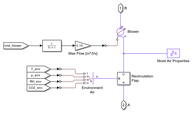
Blower Subsystem
The blower drives the air flow in the cabin HVAC loop. It is controlled to maintain the cabin temperature setpoint. The source of air can come from the environment or from recirculated cabin air.
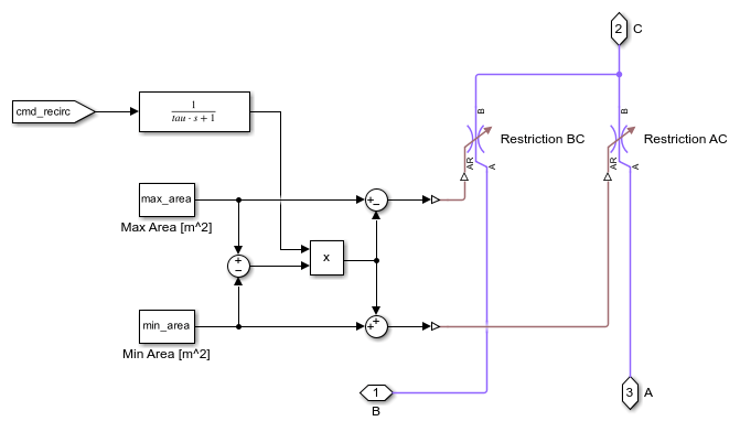
Recirculation Flap Subsystem
The recirculation flap model contains two restrictions operating in the opposite manner to send either environment air or cabin air to the blower.
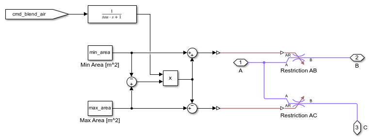
Blend Door Subsystem
The blend door is modeled as two restrictions operating in the opposite manner. In cold loop mode, the blend door directs cabin air to bypass the inner condenser. In heat pump mode, the blend door directs cabin air to pass through the inner condenser to absorb heat from the refrigerant.
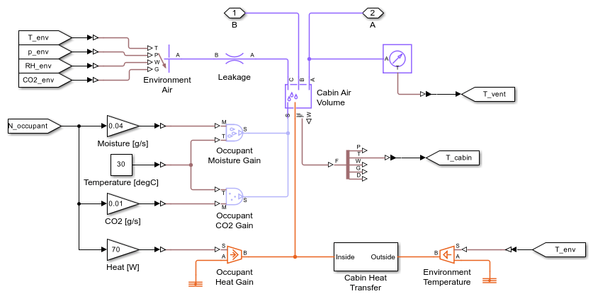
Cabin Subsystem
The vehicle cabin is modeled as a large volume of moist air. Each occupant in the vehicle is a source of heat, moisture, and CO2.
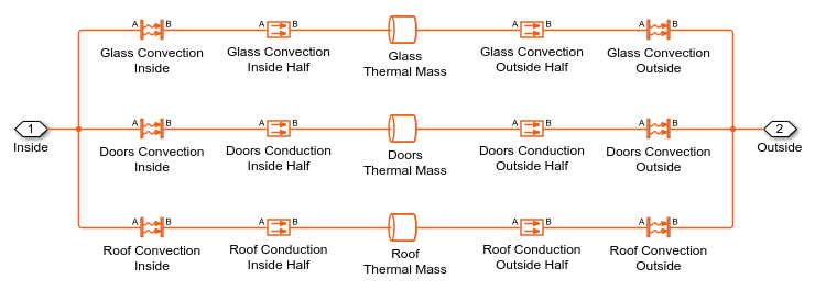
Cabin Heat Transfer Subsystem
This subsystem models the thermal resistances between the cabin interior and the external environment.
Simulation Results from Scopes
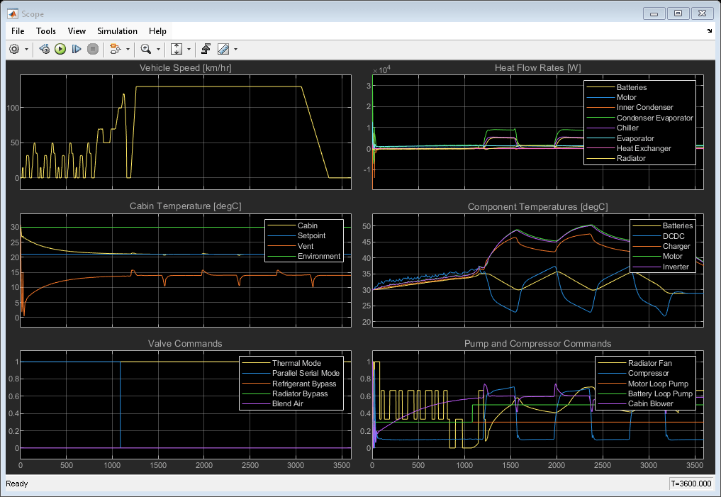
The following scope shows the vehicle speed, heat dissipation, cabin temperature, component temperatures, and control commands for the drive cycle scenario. For the Thermal Mode valve command:
0 = system off
1 = cold loop mode
2 = heat pump mode
For the Parallel Serial Mode valve command:
0 = parallel mode
1 = serial mode
At the beginning, the coolant loop is in serial mode. After about 1100 s, it switches to parallel mode and the chiller is used to keep the batteries below 35 degC. As the chiller expansion valve opens and closes to send refrigerant to the chiller, the compressor ramps up and down, respectively, to adjust to the thermal load of the batteries.
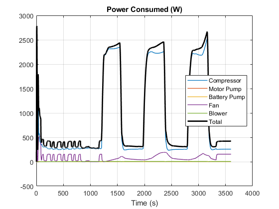
Simulation Results from Simscape Logging
This plot shows the power consumed by the thermal management system to cool the vehicle components and cabin. The largest power consumption occurs in the refrigerant compressor when the chiller expansion valve opens to allow the chiller to cool the batteries.