Pressure Reducing Valve in Punching Operation
This example models a hydraulic system with a direct operated, pressure reducing valve. This system helps to limit and maintain pressure in a hydraulic punching machine. Pressure reducing valves are common in hydraulic pressing, drilling, and stamping applications.
Model
The pressure reducing valve is upstream of the punch and downstream of the pump, pressure relief valve, and a 4-way 2-position directional valve The maximum pressure of the system is limited by the pressure relief valve.
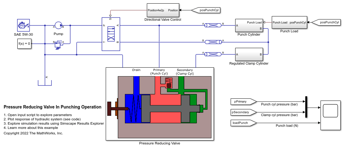
Pressure Reducing Valve Subsystem
A pressure reducing valve uses a spring-loaded spool to control the downstream pressure or the secondary pressure. If the secondary pressure is below the valve set pressure, fluid flows freely from the primary side to the secondary side. An internal passage transmits the fluid pressure from secondary side to the rightmost spool piston face. This pressure is called pilot pressure. The force due to pilot pressure opposes the spring load on the leftmost piston face. The spring may be preloaded. The spring end of the spool is connected to a drain. When the secondary pressure reaches the set pressure, the spool quickly moves to close the secondary port and thus limits and maintains secondary pressure to the set value.
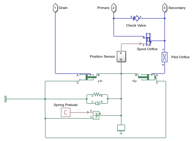
Punch Cylinder Subsystem
The punching operation has three phases. Phase one is the extension of the punch cylinder till the punch comes in contact with the metal work piece. In phase two, the punch cylinder extends more as the punch cuts through the work piece. During this phase, the pressure reducing valve controls a hydraulic clamp to keep the work piece steady. In phase three, the punch retracts. It is triggered by the control of the 4-way 2-position directional valve when the punch cylinder completes its extension stroke. A check valve present inside the reducing valve body, opens to relieve the secondary pressure during the retraction phase. The punch cylinder again starts to extend after retraction.

Punch Load Subsystem
The subsystem titled 'Punch Load' calculates the resistive force on the punch cylinder during punching operation. The example uses the work piece deformation and the stress-strain curve to calculate the punch stress. The punching area enlarges as the punch moves into the work piece while a hole is punched.

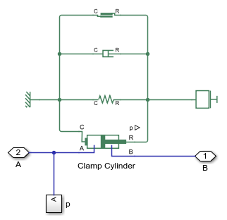
Regulated Clamp Cylinder Subsystem
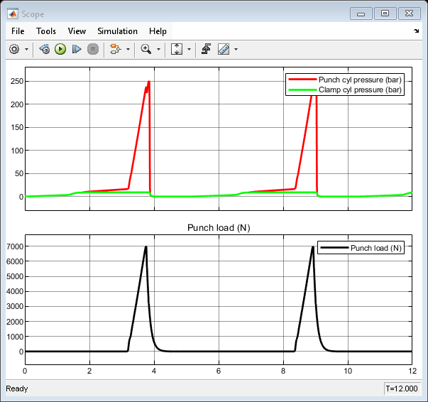
As the pump drives fluid into the punch and clamp cylinders, the pressure in the cap end chambers of both cylinders rises and both the cylinders extend. The primary port of the pressure reducing valve is connected to the cap end of the punch cylinder, and the secondary port is connected to the cap end of the clamp cylinder. As the clamp cylinder pressure reaches the set pressure of the pressure reducing valve, the spool orifice of the reducing valve closes and thus limits the clamp cylinder pressure, keeping the work piece steady. The punch cylinder pressure continues to rise till the punch stroke is completed, while the clamp cylinder pressure is maintained same.
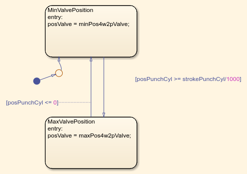
Directional Valve Control Subsystem
A motion sensor senses the punch cylinder displacement and transmits a feedback signal to the directional valve controller. This example uses a Stateflow® chart to model a simple controller that shifts the position of the directional valve. When the punch cylinder is fully retracted, or in other words, at zero displacement, flow occurs from the P port to the A port and from the B port to the T port. When the punch cylinder extends to its maximum position, the directional valve position is shifted such that flow occurs from the P port to the B port and from the A port to the T port.

Simulation Results from Scope
Simulation Results from Simscape Logging
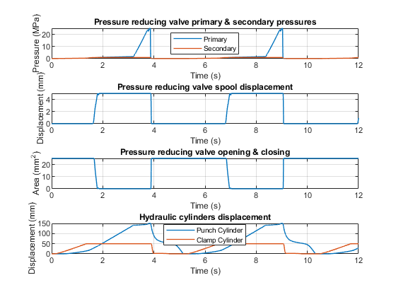
The first and topmost subplot shows the pressure variation of the punch cylinder and the clamp cylinder during extension and retraction phases. The second subplot shows the spool travel of the pressure reducing valve. The third subplot shows the spool orifice area of the valve indicating valve opening and closing. The fourth and bottommost subplot shows the displacement of the hydraulic cylinders used for punching and clamping the work piece.
See Also
Pipe (IL) | Pressure-Reducing Valve (IL)