Valves and Orifices
Use these blocks to model orifices, valves, valve actuators, and forces associated with valves and orifices in the isothermal liquid domain.
Simscape Blocks
| 2-Way Directional Valve (IL) | 2-way flow control valve in an isothermal liquid systems |
| 3-Way Directional Valve (IL) | 3-way flow control valve in an isothermal liquid system |
| 4-Way 2-Position Directional Valve (IL) | 4-way 2-position directional valve in an isothermal liquid network (Since R2021a) |
| 4-Way 3-Position Directional Valve (IL) | 4-way, 3-position directional valve in an isothermal liquid system |
| M-Way N-Position Directional Valve (IL) | M-way, N-position valve in an isothermal liquid network (Since R2022b) |
| Check Valve (IL) | Check valve in an isothermal liquid system |
| Pilot-Operated Check Valve (IL) | Check valve with pilot pressure control in an isothermal liquid system |
| Shuttle Valve (IL) | One-way switching valve in an isothermal liquid system |
| Solenoid Valve (IL) | Solenoid valve in an isothermal liquid system (Since R2023a) |
| Ball Valve (IL) | Ball valve in an isothermal liquid network (Since R2022b) |
| Cartridge Valve Insert (IL) | Cartridge flow-control valve in an isothermal liquid network |
| Gate Valve (IL) | Gate valve in an isothermal liquid system |
| Needle Valve (IL) | Needle valve in an isothermal liquid system |
| Poppet Valve (IL) | Poppet valve in an isothermal liquid network |
| Pressure-Compensated 3-Way Flow Control Valve (IL) | 3-way flow control in an isothermal liquid system |
| Pressure-Compensated Flow Control Valve (IL) | Flow control with pressure regulation in an isothermal liquid system |
| Counterbalance Valve (IL) | High-pressure regulation valve in an isothermal liquid system |
| Pressure Relief Valve (IL) | Pressure-relief valve in an isothermal liquid network |
| Pressure-Reducing Valve (IL) | Pressure-reducing valve in an isothermal liquid network |
| Pressure-Reducing 3-Way Valve (IL) | Combined pressure-relief and pressure-reducing valve in an isothermal liquid system |
| Pressure Compensator Valve (IL) | Pressure compensator valve in an isothermal liquid network |
| Cartridge Valve Actuator (IL) | Actuator that maintains equilibrium between valve and pilot pressures in an isothermal liquid system |
| Double-Acting Servo Valve Actuator (IL) | Double-acting servo cylinder with spring-centered spool in an isothermal liquid system |
| Pilot Valve Actuator (IL) | Single-acting or double-acting actuator controlled by a pilot pressure in an isothermal liquid network |
| Spool Orifice Flow Force (IL) | Axial fluid force on spool orifice in an isothermal liquid system |
| Multiposition Valve Actuator | Multiposition actuator in any fluid domain |
| Proportional Valve Actuator | Power-controlled valve actuator in any fluid domain |
| Annular Leakage (IL) | Models annular leakage between a circular tube and a round insert in an isothermal flow |
| Orifice (IL) | Constant-area or variable-area orifice in an isothermal liquid system |
| Spool Orifice (IL) | Variable-area spool orifice in an isothermal liquid system |
| Variable Overlapping Orifice (IL) | Orifice created by open segments with variable overlap in an isothermal liquid system |
Topics
- Modeling Directional Valves in Simscape Fluids
Selecting and parameterizing directional control valves in Simscape™ Fluids™.
- Building a Custom Valve
Model a custom valve with orifice blocks.
- Parameterize an M-Way N-Position Valve
Use a data sheet to parameterize an M-Way N-Position Valve (IL).
Featured Examples
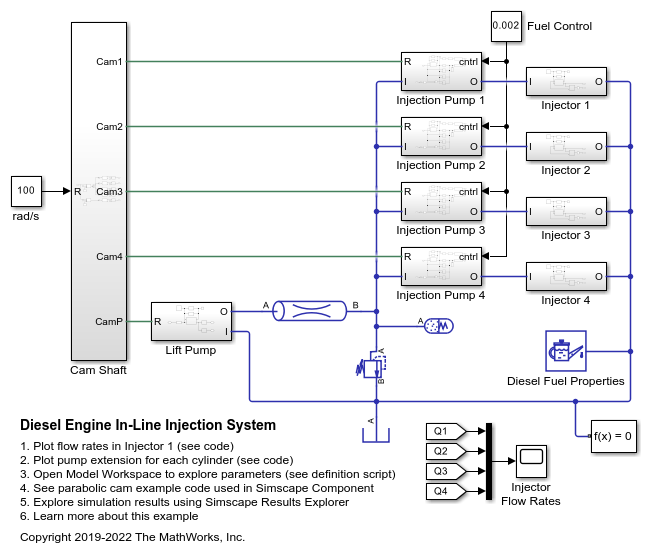
Diesel Engine In-Line Injection System
An in-line multi-element diesel injection system. It consists of a cam shaft, a lift pump, four in-line injection pumps, and four injectors.
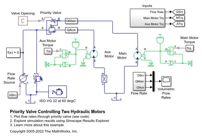
Priority Valve Controlling Two Hydraulic Motors
A pressure-compensated 3-way flow control valve. This valve maintains constant flow rate through the main hydraulic motor, which is connected to the pressure-compensated outlet of the flow control valve. It acts as a priority valve, diverting the excess flow to the auxiliary hydraulic motor if the main hydraulic motor receives enough fluid to maintain a preset angular velocity. The auxiliary motor is shut off completely if there is insufficient flow to power the main hydraulic motor.
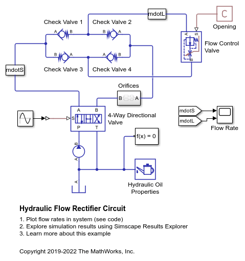
Hydraulic Flow Rectifier Circuit
A flow rectifier circuit with four check valves and a flow control valve. It is used to allow a single flow control valve to control fluid flow in both directions. Similar to a Graetz circuit implemented with diodes, the check valves are arranged in such a way that flow always passes through the flow control valve in the same direction. In the Orifices subsystem, there are two more check valves that are used to select the orifice that the flow passes through depending on the flow direction.
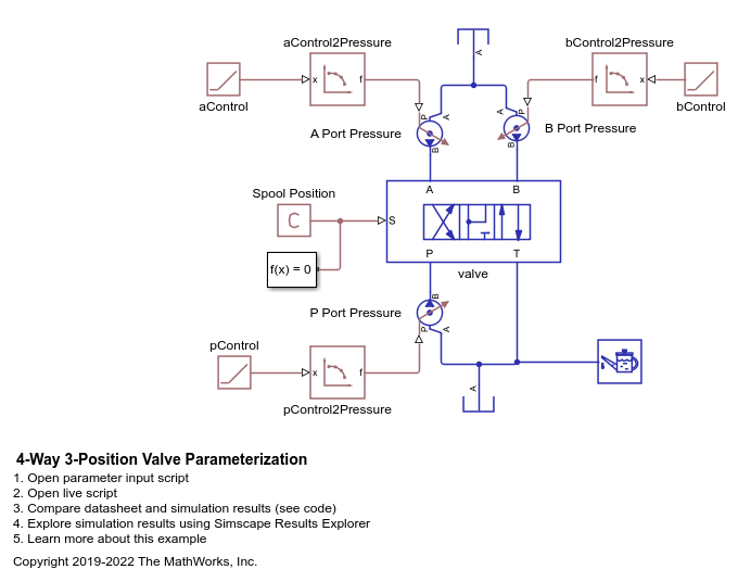
4-Way 3-Position Valve Parameterization
Parameterize and test a 4-way 3-position valve with a test harness. A plot script is provided with the example for comparing output flow between the block and data to verify the test harness. A live script is also provided with this example to explain the parameterization and the test harness workflow in detail.
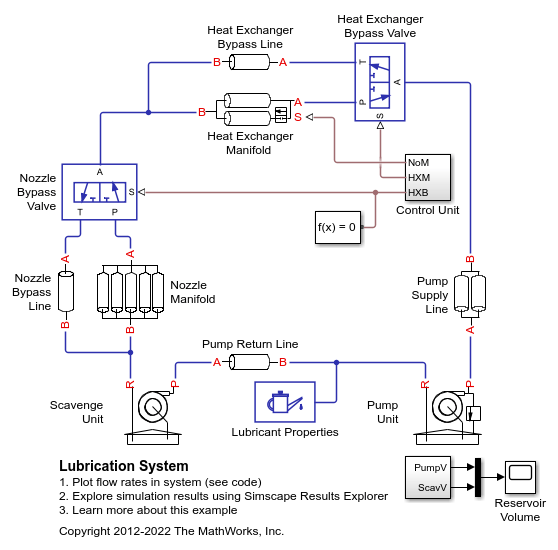
Lubrication System
A simplified version of a lubrication system fed with the centrifugal pump. The system consists of five major units: Pump Unit, Scavenge Unit, Heat Exchanger Manifold, Nozzle Manifold, and Control Unit. Both the pump and the scavenge unit are built around the centrifugal pump. The Scavenge Unit collects fluid discharged by nozzles and pumps it back into the reservoir of the Pump Unit. The Control Unit generates commands to bypass either the heat exchanger, represented as a local resistance, or the nozzles block. In a real system, these commands are generated by temperature sensors installed in lubrication cavities.
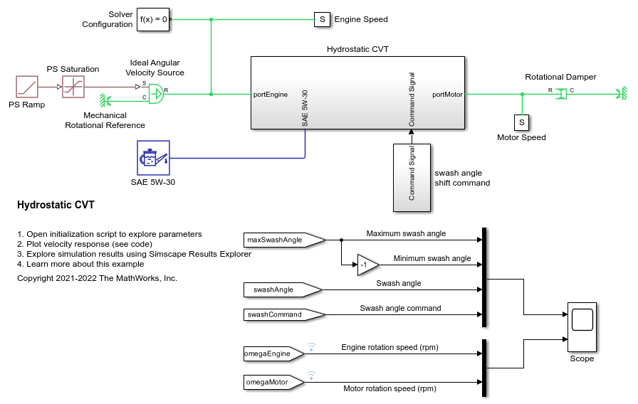
Hydrostatic CVT
Model, parameterize, and test a hydrostatic continuously variable transmission (CVT) with a swash angle shift command. When you run the plot function, it generates a comparison plot between the engine and the achieved rotational velocity in the hydraulic axial piston motor with respect to the time. Construction and agricultural equipment manufacturers use these transmissions.
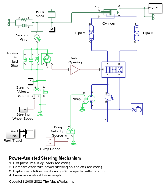
Power-Assisted Steering Mechanism
A simplified version of a power-assisted steering mechanism. The hydraulic actuation system includes a double-acting hydraulic cylinder, 4-way valve, fixed-displacement pump, and a pressure-relief valve. The steering rack acts against a load modeled by a spring and damper.
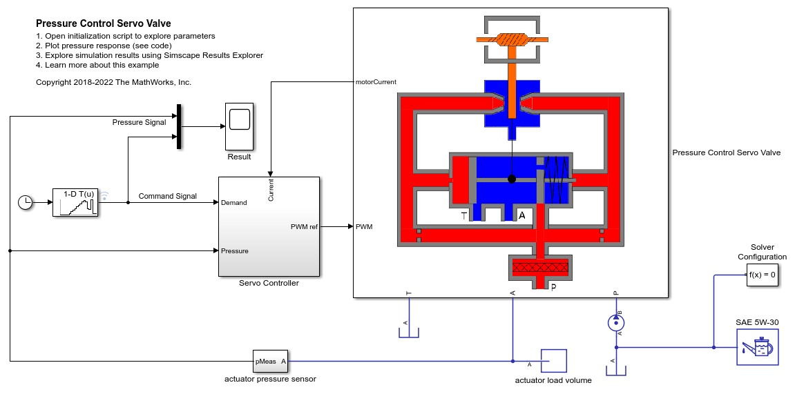
Pressure Control Servo Valve
Model, parameterize, and test a pressure control servo valve with a closed loop control. This example also generates a comparison plot between the commanded and the achieved pressure in the actuator with respect to the time. This valve provides a precise and fast control of the pressure in the actuator with a very small electrical signal to the torque motor. These valves are used in the aerospace industry and the automotive industry for the safety critical applications.
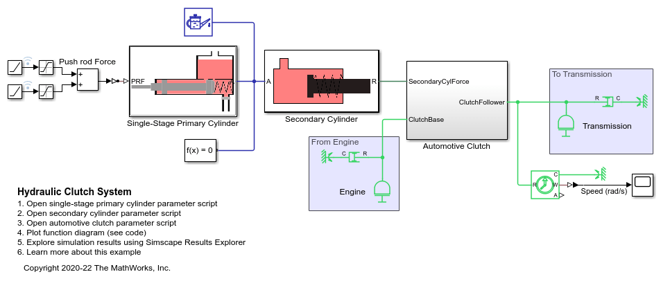
Hydraulic Clutch System
Model, parameterize, and test a hydraulic clutch system. The model is used to generate the plot of the engine and the transmission system speeds during a declutching and clutch re-engaging scenario.
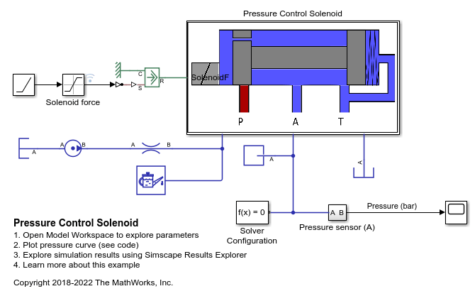
Pressure Control Solenoid
Model, parameterize, and test a pressure control solenoid valve. This example also generates a plot of the relationship between applied solenoid force and the resulting actuator port pressure.
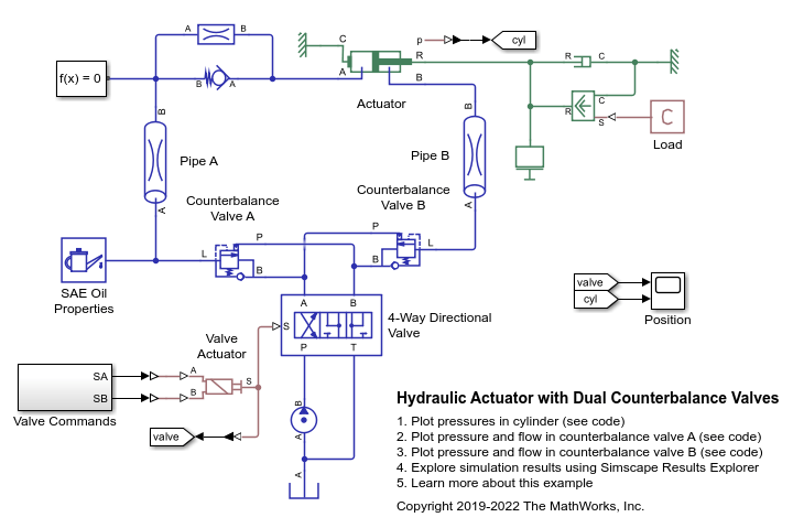
Hydraulic Actuator with Dual Counterbalance Valves
An actuator controlled by a 4-way directional valve and loaded with an overriding load, requiring the use of counterbalance valves to prevent the load from creeping when the directional valve is in the neutral position. In the neutral position, the directional valve connects ports A and B to the reservoir while blocking the pressure port P. The counterbalance valves block flow from returning to the reservoir, thus holding the actuator in place.
Hydraulic Flow Rectifier Circuit
A flow rectifier circuit with four check valves and a flow control valve. It is used to allow a single flow control valve to control fluid flow in both directions. Similar to a Graetz circuit implemented with diodes, the check valves are arranged in such a way that flow always passes through the flow control valve in the same direction. In the Orifices subsystem, there are two more check valves that are used to select the orifice that the flow passes through depending on the flow direction.
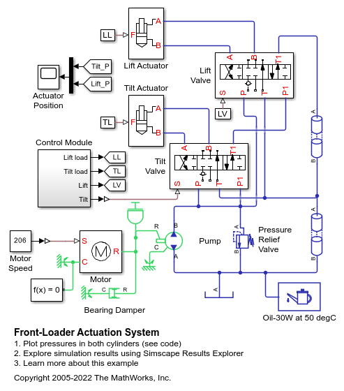
Front-Loader Actuation System
A simplified version of an actuation system consisting of the lift and tilt cylinders. Each cylinder is controlled by an open center, 6-way, 3-position directional valve. The valves are connected in series through their unloading branch such that the system pump is unloaded when both command levers are in neutral position. If either tilt or lift command is applied, the unloading path is closed.
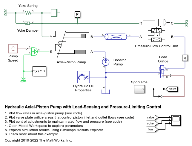
Hydraulic Axial-Piston Pump with Load-Sensing and Pressure-Limiting Control
A test rig designed to investigate the interaction between an axial-piston pump and a typical control unit simultaneously performing the load-sensing and pressure-limiting functions. To increase the fidelity of the simulation, this example uses a detailed model of the pump that accounts for the interaction between the pistons, swash plate, and valve plate.
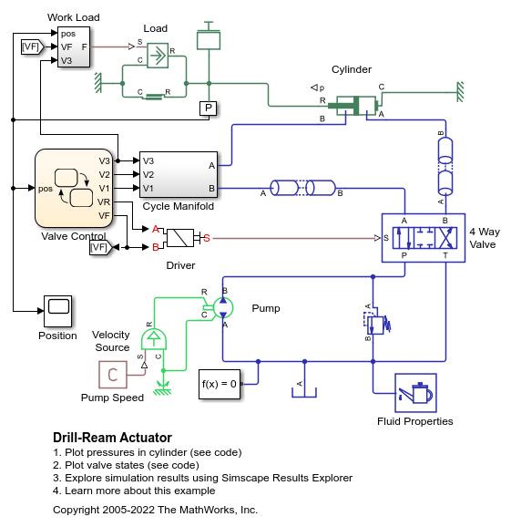
Drill-Ream Actuator
An actuator that drives a machine tool working unit performing a sequence of three technological operations: coarse drilling, fine drilling, and reaming. The actuator speed is controlled by one of three pressure-compensated flow control valves metering out return flow from the cylinder. The selection of an appropriate flow control is performed by directional valves that are activated by a control unit.
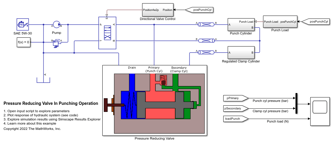
Pressure Reducing Valve in Punching Operation
Models a hydraulic system with a direct operated, pressure reducing valve. This system helps to limit and maintain pressure in a hydraulic punching machine. Pressure reducing valves are common in hydraulic pressing, drilling, and stamping applications.
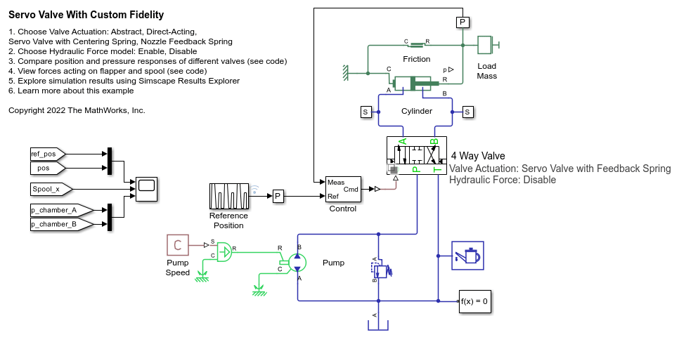
Servo Valve with Custom Fidelity
Compares the mechanical performance of various spool actuation configurations and model fidelity levels for a hydraulic 4-way 3-position directional valve. The directional valve controls a simple double-acting cylinder in a closed-loop application. This example allows you to choose among four different spool actuation designs:
ABS Open Loop Test Bench
A simple way of modeling of the anti-lock braking system (ABS) and using it with the manual braking components. The model simulates for the open loop ABS and shows the response of the pressures achieved in the caliper disc brakes. This model can be utilized in sizing of the release valve, apply valve and accumulator for the hydraulic control unit of the ABS.
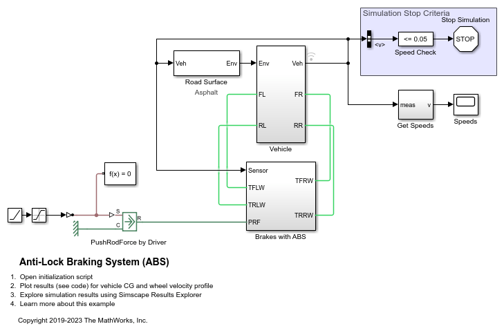
Anti-Lock Braking System (ABS)
A simple way of modeling an ABS braking system. The model shows the velocity profile responses achieved for the vehicle CG and the wheels.
MATLAB Command
You clicked a link that corresponds to this MATLAB command:
Run the command by entering it in the MATLAB Command Window. Web browsers do not support MATLAB commands.
选择网站
选择网站以获取翻译的可用内容,以及查看当地活动和优惠。根据您的位置,我们建议您选择:。
您也可以从以下列表中选择网站:
如何获得最佳网站性能
选择中国网站(中文或英文)以获得最佳网站性能。其他 MathWorks 国家/地区网站并未针对您所在位置的访问进行优化。
美洲
- América Latina (Español)
- Canada (English)
- United States (English)
欧洲
- Belgium (English)
- Denmark (English)
- Deutschland (Deutsch)
- España (Español)
- Finland (English)
- France (Français)
- Ireland (English)
- Italia (Italiano)
- Luxembourg (English)
- Netherlands (English)
- Norway (English)
- Österreich (Deutsch)
- Portugal (English)
- Sweden (English)
- Switzerland
- United Kingdom (English)
