Spool Orifice Flow Force (IL)
Axial fluid force on spool orifice in an isothermal liquid system
Libraries:
Simscape /
Fluids /
Isothermal Liquid /
Valves & Orifices /
Valve Actuators & Forces
Description
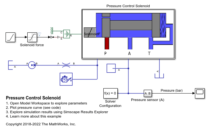
The Spool Orifice Flow Force (IL) block models the hydraulic axial force on a spool orifice. It receives the spool position as a physical signal at port S. You can also model the flow through a spool orifice with round or rectangular holes. A positive force acts to close the orifice.
If you would like to model the spool and axial force in one block, use the Spool Orifice (IL) block. The axial force is output as a physical signal at port F.
Flow Force
The force on the spool is calculated as:
where:
is the mass flow rate at port A.
ρ is the fluid density.
A is the orifice open area, which is determined by the spool position and orifice parameterization.
α is the jet angle, which is calculated from an approximation of the von Mises formula:
where c is the Radial clearance and h is the orifice opening.
ε is the opening orientation, which indicates orifice opening that is associated with a positive or negative signal at S.
Opening Area
The orifice opening is based on the open area created by the displaced spool:
where:
Smin is the Spool position at closed orifice.
S is the displacement signal at port S.
If Δs falls below 0, the orifice leakage area is used. If ΔS is greater than the Spool travel between closed and open orifice, the maximum orifice area is used.
Setting Orifice geometry to Round
holes evenly distributes a user-defined number of holes along
the sleeve perimeter that have equal diameters and centers aligned in the same
plane.
The open area is
where:
n0 is the number of holes.
d0 is the diameter of the holes.
θ is the orifice opening angle:
If θ is greater than 2π, θ remains at 2π.
Aleak is the Leakage area.
The open area expression is based on a geometric derivation and calculates the area of each hole as a planar circle. If the sleeve is cylindrical, the holes are not planar and this expression is an approximation.
The maximum open area is:
Setting Orifice geometry to Rectangular
slot models one rectangular slot in the tube sleeve.
For an orifice with a slot in a rectangular sleeve, the open area is
where w is the orifice width.
The maximum opening distance between the sleeve and case is:
where ΔSmax is the Spool travel between closed and open orifice.
Numerically-Smoothed Displacement
At the extremes of the orifice opening range, you can maintain numerical robustness in your simulation by adjusting the block Smoothing factor. The block applies a smoothing function to every calculated displacement, but primarily influences the simulation at the extremes of this range.
If the Smoothing factor
parameter is nonzero, the block smoothly saturates the orifice opening between
0 and ΔSmax where
ΔSmax is the:
Value of the Diameter of round holes parameter, when Orifice parameterization is set to
Round holes.Value of the Spool travel between closed and open orifice parameter, when Orifice parameterization is set to
Rectangular slot.
For more information, see Numerical Smoothing.
Assumptions and Limitations
The transient effects are negligible.
The jet angle approximation is based on the Richard von Mises equation.
The jet angle variation with the orifice opening is identical for the rectangular slot and the round holes orifices.
Examples
Ports
Conserving
Input
Output
Parameters
References
[1] Manring, N. Hydraulic Control Systems. John Wiley & Sons, 2005.
[2] Merritt, H. Hydraulic Control Systems. Wiley, 1967.
Extended Capabilities
Version History
Introduced in R2020a

