Rotating Hydraulic Actuator
This example uses a Rotating Single-Acting Actuator (IL) block to model a hydraulic cylinder actuator for operating friction clutches, brakes, and other devices installed on rotating shafts. A key element of the actuator is a piston that moves back and forth under an axial force that consists of the static pressure force and a rotating cylinder force developed by centrifugal force on the rotating fluid.
Model
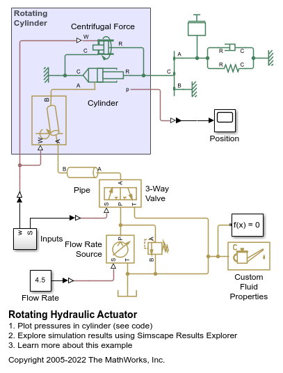
In the model, the actuator acts against a preloaded spring, which tends to retract the piston. The pump delivers 4.5 l/min to the hydraulic system, and the pressure relief valve has the set pressure differential of 10 bar. The 3-way directional valve controls the actuator, connecting the actuator to the pump or the tank depending on the control signal applied.
The following figure shows a cross-section diagram of the rotating hydraulic actuator:

 - Internal piston radius
 - External piston radius
 ,
,  - Arm lengths of the lever
The schematic below shows a network equivalent to the actuator block.

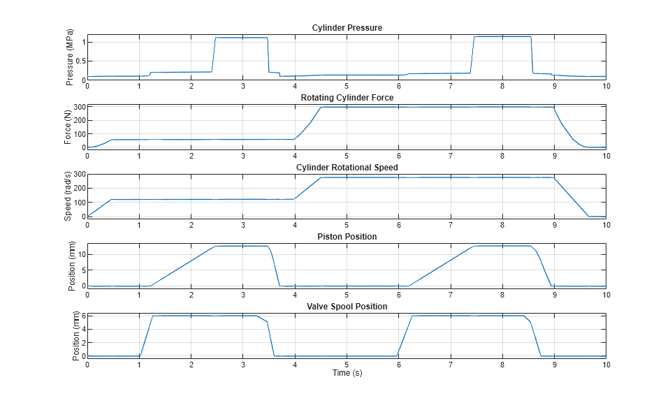
Simulation Results from Scopes

Simulation Results from Simscape Logging
The example simulates two actuator cycles. The two strokes occur with rotational speeds of 120 rad/s and 275 rad/s, respectively. The first two plots below show the cylinder pressure, which generates the static pressure force, and the rotating cylinder force, which is caused by the centrifugal force acting on the fluid within the cylinder. Because of the higher rotational speed, the second stroke exhibits a higher cylinder pressure and a higher rotating cylinder force.