Actuation
In this section, you can find examples of actuation systems in multiple Simscape Fluids domains.
Featured Examples
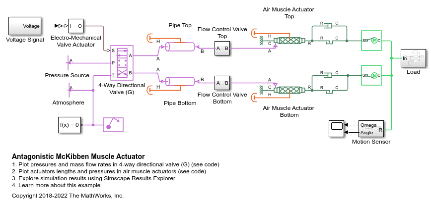
Antagonistic McKibben Muscle Actuator
This demo shows a muscle actuation based on two air muscle actuators (or McKibben artificial muscles) in antagonistic connection. The air muscle actuators are connected to the opposite sides of a lever. The 4-way directional valve is controlled by an electro-mechanical valve actuator. In the 4-way directional valve when the high-pressure path P-A and return line B-T are open, the top air muscle actuator contracts and forces the bottom air muscle actuator on the opposite side to extend. Similarly, as the high-pressure path P-B and return line A-T open, the bottom air muscle actuator starts to contract and forces the top air muscle actuator to extend. The oscillating motions of the muscles are converted into the angular rotation of the output load connected to the mechanical linkage modeled with the slider-cranks.
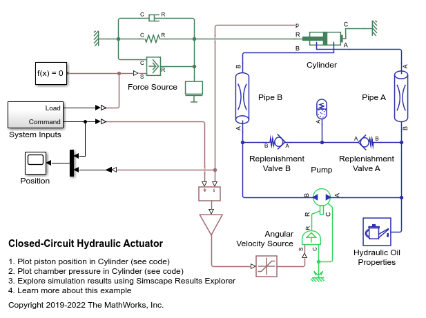
Closed-Circuit Hydraulic Actuator
A closed-circuit hydraulic actuator driven by a variable-speed pump. The actuator is arranged as a closed fluid system with two replenishment valves (check valves) and a spring-loaded accumulator serving as a replenishment reservoir. The pump speed is controlled by the difference between the commanded and measured piston position. The actuator acts against a spring, a damper, and a time-varying load.
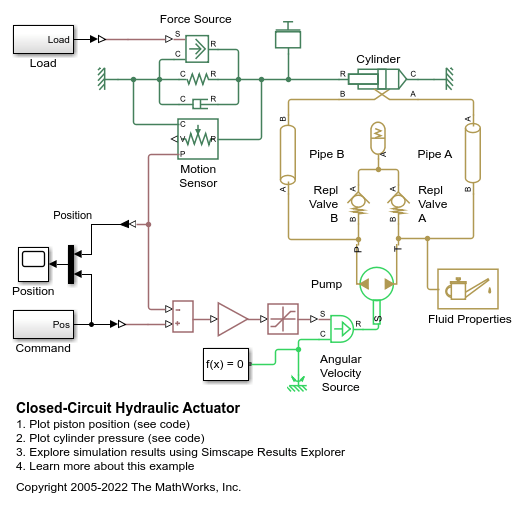
Closed-Circuit Hydraulic Actuator
Warning: This example uses the hydraulic domain, which will be removed in a future release. Find an equivalent example model that uses the isothermal liquid domain here: Closed-Circuit Hydraulic Actuator. To convert models to the isothermal liquid domain, use the hydraulicToIsothermalLiquid tool.
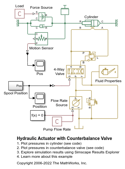
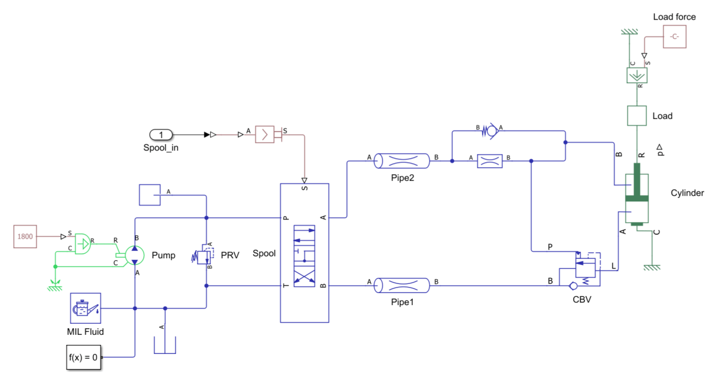
Hydraulic Actuator with Counterbalance Valve
The model demonstrates extension, retraction, and holding of a hydraulic actuator with a counterbalance valve. An open-center 4-way directional valve controls a double-acting actuator, and a constant flow rate source equipped with a pressure relief valve serves as the power unit. The actuator is subject to an external force that tries to extend the actuator. The counterbalance valve modulates the return flow into port L, preventing the loss of control of the actuator in extending, as well as holding the piston in place at the neutral position of the valve. Port A of the actuator connects to port P of the counterbalance valve, making it impossible for the cylinder to move until the pressure at port A builds up to a certain level.
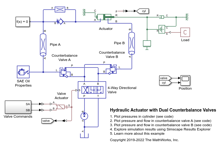
Hydraulic Actuator with Dual Counterbalance Valves
An actuator controlled by a 4-way directional valve and loaded with an overriding load, requiring the use of counterbalance valves to prevent the load from creeping when the directional valve is in the neutral position. In the neutral position, the directional valve connects ports A and B to the reservoir while blocking the pressure port P. The counterbalance valves block flow from returning to the reservoir, thus holding the actuator in place.
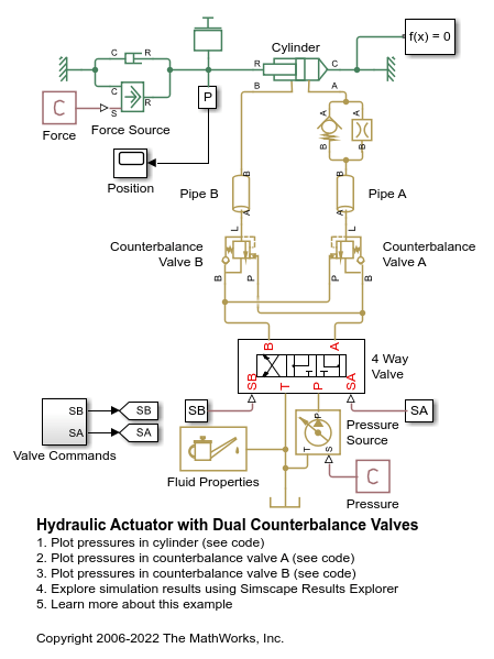
Hydraulic Actuator with Dual Counterbalance Valves
Warning: This example uses the hydraulic domain, which will be removed in a future release. Find an equivalent example model that uses the isothermal liquid domain here: Hydraulic Actuator with Dual Counterbalance Valves. To convert models to the isothermal liquid domain, use the hydraulicToIsothermalLiquid tool.

Hydraulic Actuator with Telescopic Cylinder
Demonstrates the extension and retraction of a telescopic hydraulic actuator with three stages. The telescopic actuator extends and retracts one stage at a time.

Hydraulic Cylinder with Cylinder Cushions
A hydraulic double-acting actuator equipped with cushions on both end stops. The cushions serve as hydraulic brakes when the piston approaches the stops, absorbing some of the kinetic energy of the system before the piston touches the stops. For more information, see Double-Acting Actuator (IL).
Configure a Hydraulic Lift Model for Real-Time Simulation
Configure a model for real-time simulation. To simulate in real-time, you must convert the model into a fixed-step model. In this example, you choose a step size, convert the model, examine the results, and test and adjust the model robustness.
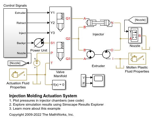
Injection Molding Actuation System
An injection molding actuation system. The model contains a set of cartridge valves that control pumps, motors, and cylinders to execute the steps of an injection molding process.
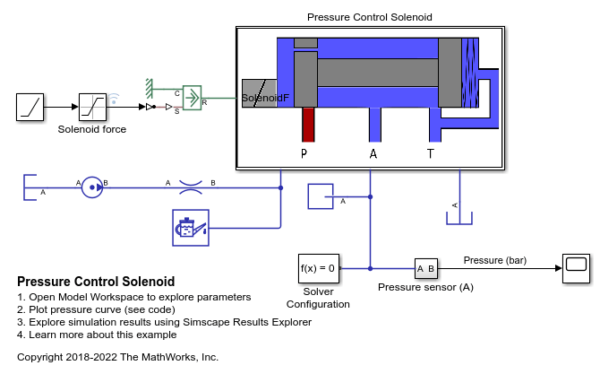
Pressure Control Solenoid
Model, parameterize, and test a pressure control solenoid valve. This example also generates a plot of the relationship between applied solenoid force and the resulting actuator port pressure.
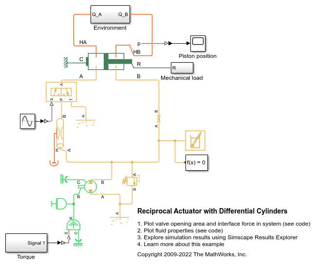
Reciprocal Actuator with Differential Cylinders
A double-acting actuator with differential cylinders. The pump output is connected to cylinder B of the actuator while cylinder A of the actuator can be connected to either the pump or the reservoir through the 3-way directional valve. When cylinder A is connected to the pump, pressures at both cylinders become equal. Because of the larger effective piston area in cylinder A, the interface force in cylinder A is larger than that of in cylinder B which causes the piston to extend. When cylinder A is connected to the reservoir, the piston starts to retract. The 3-way directional valve is controlled by a sinusoidal signal to achieve repeating reciprocal motion in the actuator.
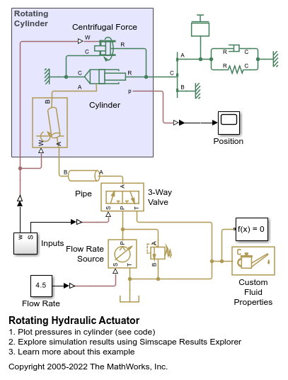
Rotating Hydraulic Actuator
Uses a Rotating Single-Acting Actuator (IL) block to model a hydraulic cylinder actuator for operating friction clutches, brakes, and other devices installed on rotating shafts. A key element of the actuator is a piston that moves back and forth under an axial force that consists of the static pressure force and a rotating cylinder force developed by centrifugal force on the rotating fluid.
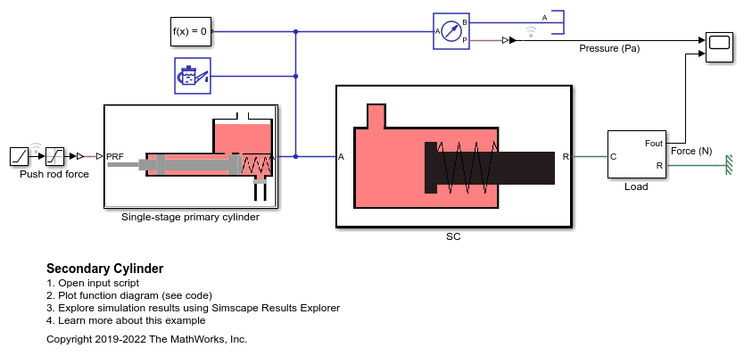
Secondary Cylinder
Model, parameterize and, test a secondary cylinder. Given the numerical data extracted from the datasheet of the single-stage primary cylinder, the unknown parameters of the secondary cylinder are calculated. The model is simulated to generate the plot between the applied force to the single-stage primary cylinder and the pressure developed inside the secondary cylinder.
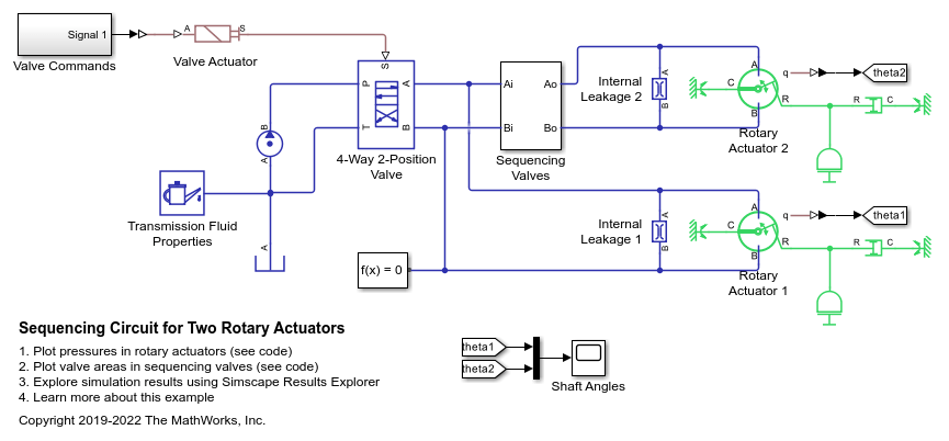
Sequencing Circuit for Two Rotary Actuators
A sequencing circuit that is based on four check valves installed in the pressure and return lines of the second rotary actuator. The cracking pressure of the meter-in check valves is set high enough to prevent flow into rotary actuator 2 while rotary actuator 1 is rotating, but lower than the pressure that develops once rotary actuator 1 reaches its hard stop. As a result, rotary actuator 2 starts moving only after rotary actuator 1 completes its stroke.
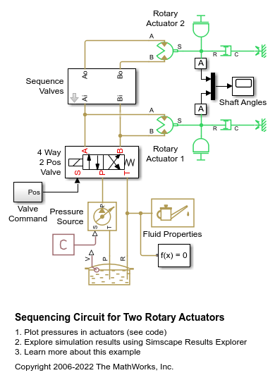
Sequencing Circuit for Two Rotary Actuators
Warning: This example uses the hydraulic domain, which will be removed in a future release. Find an equivalent example model that uses the isothermal liquid domain here: Sequencing Circuit for Two Rotary Actuators. To convert models to the isothermal liquid domain, use the hydraulicToIsothermalLiquid tool.
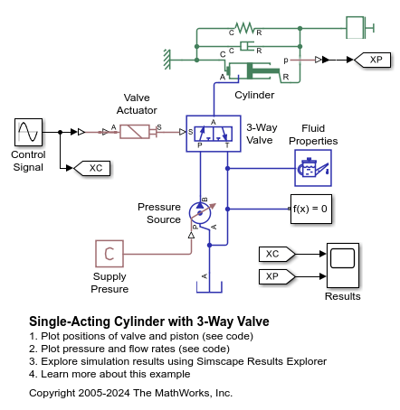
Single-Acting Cylinder with 3-Way Valve
A single-acting hydraulic cylinder controlled by a 3-way directional valve. The mass, viscous friction, and preloaded spring blocks represent the load. The pump is powerful enough to maintain constant pressure at the valve inlet. The signal from a Multiposition Valve Actuator block (Valve Actuator) controls the spool position of a 3-Way Directional Valve (IL) block (3-Way Valve).
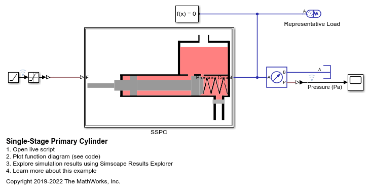
Single-Stage Primary Cylinder
Model, parameterize, and test a single-stage primary cylinder starting from manufacturer datasheet information. Given the numerical data extracted from the datasheet, the unknown parameters are calculated. The model is then simulated and the resulting push rod force versus pressure relationship curve is compared with curve provided on the manufacturer datasheet.
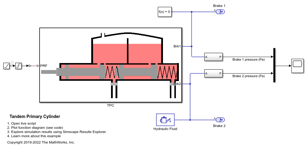
Tandem Primary Cylinder
Model, parameterize and test a tandem primary cylinder starting from manufacturer datasheet information. First, there is a brief discussion on the mathematical modeling of the system. Given the numerical data extracted from the datasheet, optimization is then used to determine remaining unknown parameters. The model is then simulated and the resulting push rod force - brake pressure relationship curve is compared with the curve provided on the manufacturer datasheet. Understanding the behavior of the tandem primary cylinder is an important prerequisite to selection of other braking system components.