Test Harnesses and Parameterization
In this section, you can find test harnesses or parameterization examples multiple Simscape Fluids domains.
Featured Examples
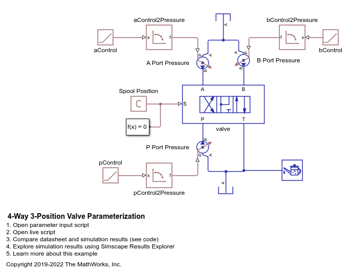
4-Way 3-Position Valve Parameterization
Parameterize and test a 4-way 3-position valve with a test harness. A plot script is provided with the example for comparing output flow between the block and data to verify the test harness. A live script is also provided with this example to explain the parameterization and the test harness workflow in detail.
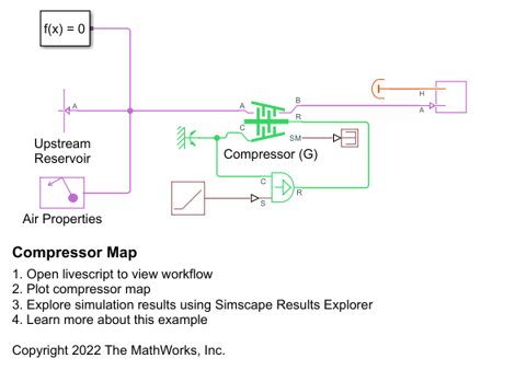
Compressor Map
Create the pressure ratio, corrected mass flow rate, and efficiency tables required to specify the performance characteristics of a dynamic compressor.
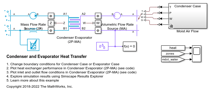
Condenser and Evaporator Heat Transfer
Models a condenser or an evaporator in simple test setup with R134a refrigerant on the left side and moist air on the right side. It has a cross flow arrangement with the moist air blowing across tube banks filled with the refrigerant.
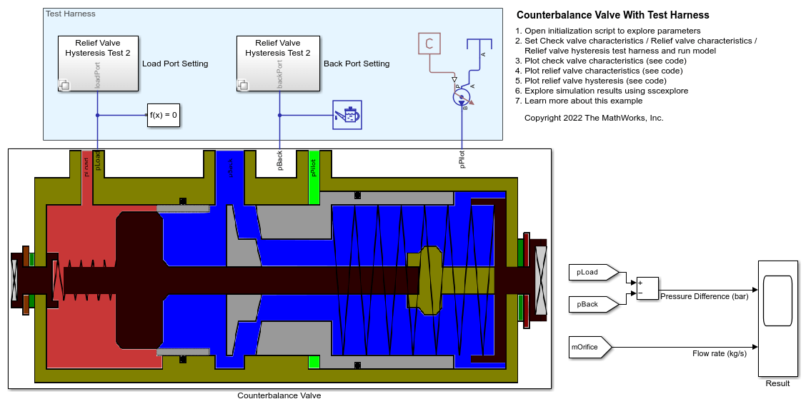
Counterbalance Valve with Test Harness
Model, parameterize, and test a counterbalance valve in detailed fidelity and system level fidelity using a variant subsystem. Running the model generates a plot of the flow from the load port to the back port due to the relief action of the counterbalance valve using the detailed fidelity variant. A counterbalance valve allows an upstream flow from the back port to the load port through the check valve stage, and it allows a downstream flow from the load port to the back port through the relief stage. Counterbalance valves help with load holding, load actuation speed control, and safety.
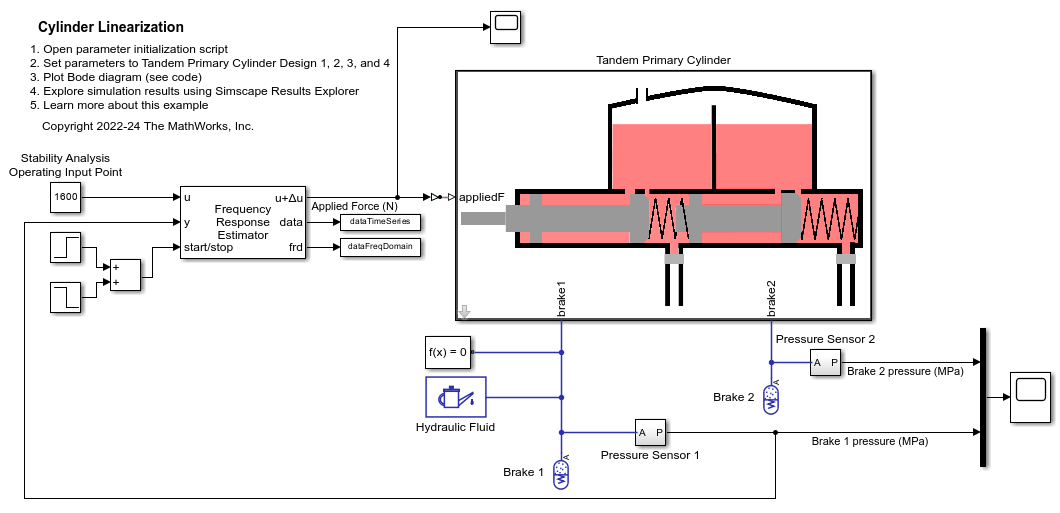
Cylinder Linearization
Linearize a Simscape™ hydro-mechanical system model to check stability of an open-loop system around an operating point. This example uses the Simulink Control Design™ Frequency Response Estimator block to perform a frequency response estimation experiment and store the data for later estimation offline.
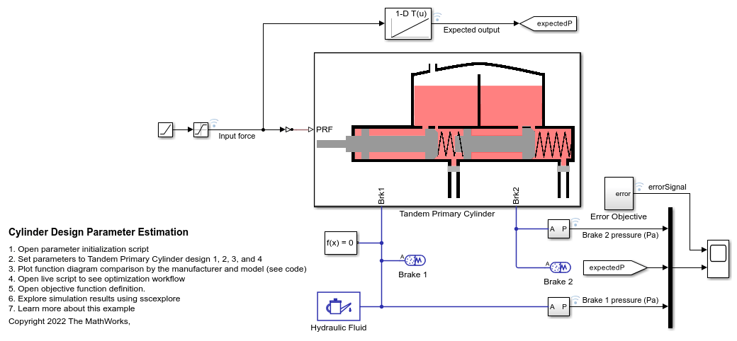
Cylinder Design Parameter Estimation
Parameterize and test a tandem primary cylinder starting from a manufacturer datasheet. This example uses optimization to determine remaining unknown parameters, given the numerical data extracted from the datasheet. After the model is simulated, it compares the resulting push rod force - brake pressure relationship curve to the curve provided on the manufacturer datasheet. Understanding the behavior of the tandem primary cylinder is important when selecting other braking system components.
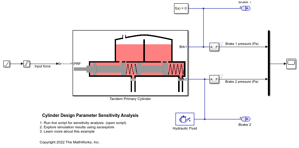
Cylinder Design Parameter Sensitivity Analysis
Perform a sensitivity analysis for tandem primary cylinder model in Simscape™. The example requires the Simulink® Design Optimization™ to be installed and licensed to run.
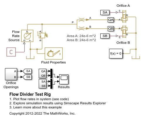
Flow Divider Test Rig
Warning: This example uses the hydraulic domain, which will be removed in a future release. Find an equivalent example model that uses the isothermal liquid domain here: Flow Divider. To convert models to the isothermal liquid domain, use the hydraulicToIsothermalLiquid tool.
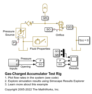
Gas-Charged Accumulator Test Rig
A test rig for the Gas-Charged Accumulator (IL) block. The pressure source with the orifice closed charges the accumulator. The check valve holds the accumulator at its charged pressure, and as the orifice opens the accumulator discharges.
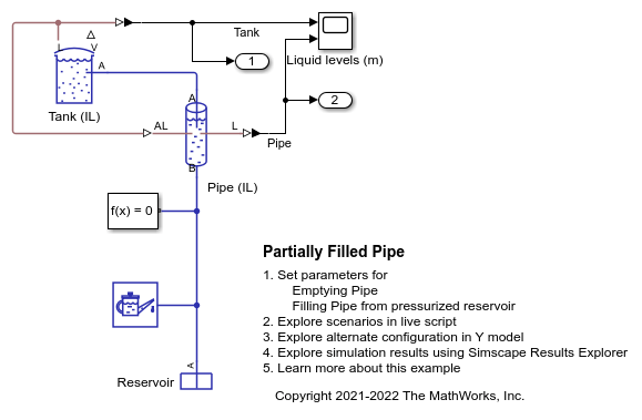
Partially Filled Pipe
The Partially Filled Pipe (IL) block used to model the emptying and filling of a tank in multiple configurations. You can use the live script provided with this example to understand the effect of different configurations.
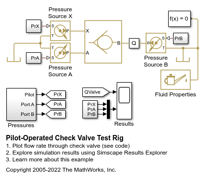
Pilot-Operated Check Valve Test Rig
A test rig for the Pilot-Operated Check Valve (IL) block. The valve connects to three ideal pressure sources, two of which create the pressure differential across the main flow line, while the third applies pressure to the pilot port X. This pressure allows flow through the valve even if the main pressure differential is negative.
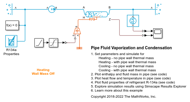
Pipe Fluid Vaporization and Condensation
The 3-Zone Pipe (2P) block used to model vaporization or condensation of fluid flow in a pipe. The block divides the internal fluid volume into up to three zones: liquid zone, mixture zone, and vapor zone, depending on the state of the fluid along the pipe. As fluid flows through the pipe, heat is transferred between the environment external to the pipe and the fluid inside the pipe, causing it to change from liquid to mixture to vapor for the heating case or from vapor to mixture to liquid for the cooling case. The effect of thermal storage in the pipe wall can be optionally turned on by specifying a nonzero pipe wall thickness.
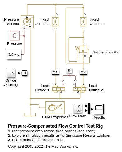
Pressure-Compensated Flow Control Test Rig
A test rig for the Pressure Compensator Valve (IL) block. A constant-pressure source connects to two flow paths that each have a fixed orifice and a variable orifice which acts as a variable load. One flow path contains a pressure compensator valve.
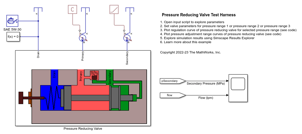
Pressure Reducing Valve Test Harness
Model, parameterize, and test a pressure reducing valve. The model is used to generate a plot of the regulation curve i.e. a plot of flow vs regulated pressure. This plot can be compared with the characteristics from the manufacturer datasheet to verify the test harness. The regulation curve displays two valve functions namely the reducing function and the relieving function. The reducing valve remains open when the pressure at the secondary port is less than a specified pressure, known as the set pressure. When the pressure at the secondary port meets or surpasses the set pressure, the reducing valve closes. In the regulation curve, the region of positive flow represents the phase when the reducing valve is open and gradually closes. The pressure reducing valve used in this example has a check valve that relieves pressure when the secondary pressure is about to surpass the set pressure. During this phase, the hydraulic fluid escapes via the check valve to the primary port keeping the secondary pressure constant at the set pressure. The region of negative flow in the regulation curve represents the phase when the pressure reducing valve is closed and the check valve opens gradually. Pressure reducing valves are used in industry to limit and maintain pressure during operations like hydraulic pressing, punching, drilling and stamping.

Pressure Relief Valve Test Rig
A test rig to check the pressure-flow characteristic of the Pressure Relief Valve (IL) block. A pressure relief valve and a variable orifice connect to a constant flow rate source in parallel. As the orifice closes, pressure gradually builds up and eventually reaches the set pressure differential of the pressure relief valve. At this pressure, the valve begins to divert flow to the tank and regulates the pressure at the source outlet. As the orifice opens again, the pressure relief valve closes and the entire flow passes through the variable orifice.
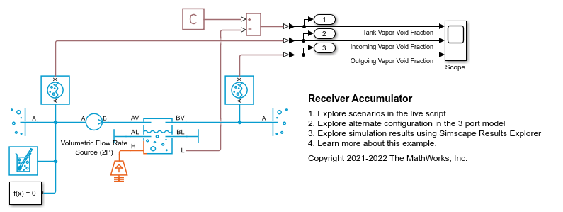
Receiver Accumulator
The liquid and vapor separation using the Receiver Accumulator (2P) block. The Receiver Accumulator (2P) block models a container of fluid in a two-phase fluid network with separate liquid and vapor ports. In an HVAC system, when this tank is placed between a condenser and an expansion valve, it acts as a receiver. Liquid connections to the block are made at ports AL and BL. When the tank is placed between an evaporator and a compressor, it acts as an accumulator. Vapor connections to the block are made at ports AV and BV. The fluid in the container can be fully liquid, fully vapor, or a mixture of both. Mass and energy exchange can occur between the fluid phases due to vaporization and condensation.

Segmented Pipeline Test Rig
Warning: This example uses the hydraulic domain, which will be removed in a future release. Find an equivalent example model that uses the isothermal liquid domain here: Water Hammer Effect. To convert models to the isothermal liquid domain, use the hydraulicToIsothermalLiquid tool.
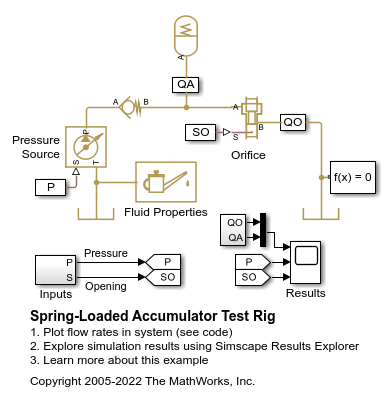
Spring-Loaded Accumulator Test Rig
A test rig for the Spring-Loaded Accumulator (IL) block. When the orifice is closed, the pressure source charges the accumulator. The check valve holds the accumulator at its charged pressure, and as the orifice opens the accumulator discharges.