Receiver Accumulator
R2026bThis example shows the liquid and vapor separation using the Receiver Accumulator (2P) block. The Receiver Accumulator (2P) block models a container of fluid in a two-phase fluid network with separate liquid and vapor ports. In an HVAC system, when this tank is placed between a condenser and an expansion valve, it acts as a receiver. Liquid connections to the block are made at ports AL and BL. When the tank is placed between an evaporator and a compressor, it acts as an accumulator. Vapor connections to the block are made at ports AV and BV. The fluid in the container can be fully liquid, fully vapor, or a mixture of both. Mass and energy exchange can occur between the fluid phases due to vaporization and condensation.
The physical signal port L of the Receiver Accumulator (2P) block reports the liquid volume fraction of the total container volume. In this example the vapor volume fraction of the signals connected to the receiver accumulator are reported using Vapor Quality Sensors. To create comparable plots for all the monitored values, the Vapor Quality sensor are set to report the vapor void fraction in the signals and the liquid volume fraction reported from the tank is converted to vapor volume fraction using a PS Subtract block.
Simple Two Port Configuration
This model demonstrates the basic function of the Receiver Accumulator (2P) block by connecting two of the four ports of the block. Fluid with a low void fraction is sent into port AV. Open the model.
open_system("ReceiverAccumulator")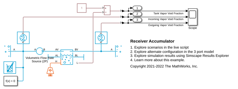
Define operating conditions.
wallTemperature = 373.1;     % Temperature of system (K)
volumetricFlow = 0.01;       % Volumetric flow rate of incoming fluid (m^3/s)
incomingVaporFraction = 0;   % Vapor void fraction of the incoming fluid
initialVaporFraction = 1;    % Starting vapor void fraction of the receiver accumulator
Run the model and plot the results. The plot shows that regardless of the void fraction inside the Receiver Accumulator (2P) block, port BV outputs only vapor, provided there is some vapor present in the tank.
open_system("ReceiverAccumulator/Scope")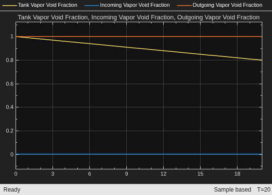
sim("ReceiverAccumulator");You can explore this block further by trying different flow rates or different incoming vapor qualities. For example, try setting the volumetric flow to 0.05 m^3/s, or the incoming vapor void fraction to 0.1.
Three Port Configuration
This configuration shows the Receiver Accumulator (2P) block with three ports connected, one incoming port and two outgoing ports. This model shows the separation of the liquid and vapor within the Receiver Accumulator (2P) block. It can be seen that as the vapor void fraction in the tank changes the vapor void fraction at ports and the mass flow rate out of the ports AV and BV remain constant and the mass flow rate out of the ports changes to adjust for the vapor void fraction of the tank. Open the model.
open_system("ReceiverAccumulatorThreePort")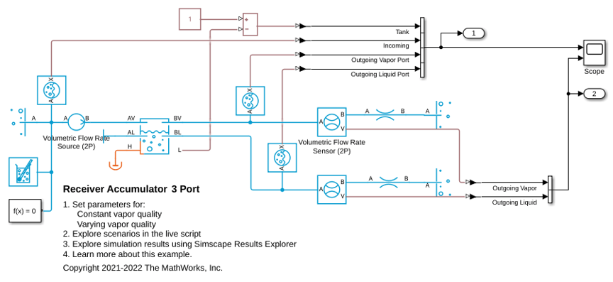
Run the model with consistent initial and incoming vapor void fractions. This scenario shows the three port configuration using the same initial vapor void fraction in the tank as the incoming vapor void fraction.
Define the parameters.
volumetricFlow3 = 0.005;         % Volumetric flow rate of incoming fluid (m^3/s)
incomingVaporFraction3 = 0.2;   % Vapor volume fraction of the incoming fluid
initialVaporFraction3 = 0.2;    % Starting vapor volume fraction of the receiver accumulator
Run the model and plot the results.
open_system("ReceiverAccumulatorThreePort/Scope")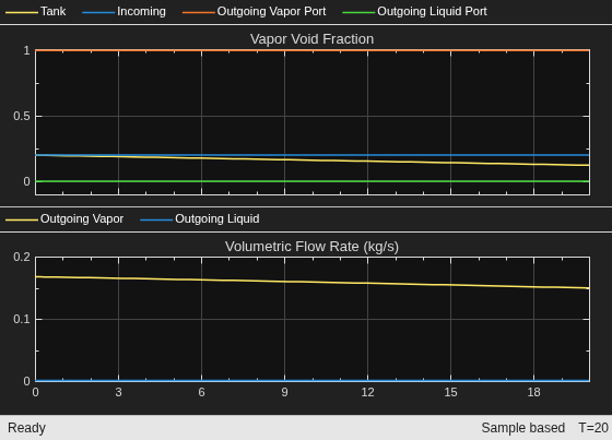
sim("ReceiverAccumulatorThreePort");You might expect to see the vapor void fraction stay the same in the tank throughout the simulation; however, you can see that the vapor void fraction in the tank decreases over the course of the simulation, because fluid is only exiting the vapor port.
Next, run the model with varying initial and incoming vapor void fractions. This scenario shows the three port configuration using a higher initial vapor void fraction in the receiver accumulator than the incoming vapor void fraction.
Define the parameters.
volumetricFlow3 = 0.01;         % Volumetric flow rate of incoming fluid (m^3/s)
incomingVaporFraction3 = 0.2;   % Vapor volume fraction of the incoming fluid
initialVaporFraction3 = 0.8;    % Starting vapor volume fraction of the receiver accumulator
Run the model and plot results.
sim("ReceiverAccumulatorThreePort");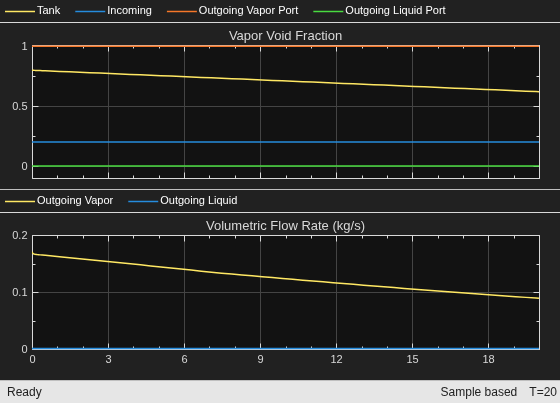
As the receiver accumulator vapor void fraction decreases, the flow rate of the outgoing liquid increases.
See Also
Receiver Accumulator (2P) | 3-Zone Pipe (2P)

