Warp Blocked Image at Coarse and Fine Resolution Levels
This example shows how to apply a geometric transformation (warping) to a blocked image.
Applying a geometric transformation to an image is a key step in many image processing applications like image registration. You can use imwarp to warp coarse images that fit in memory. For large, high-resolution images that do not fit in memory, use a blocked image. Set the spatial referencing of the warped image to preserve characteristics of the image such as pixel extents.
Create a blocked image using a modified version of image "tumor_091.tif" from the CAMELYON16 data set. The original image is a training image of a lymph node containing tumor tissue. The original image has eight resolution levels, and the finest level has resolution 53760-by-61440. The modified image has only three coarse resolution levels. The spatial referencing of the modified image has been adjusted to enforce a consistent aspect ratio and to register features at each level.
bim = blockedImage("tumor_091R.tif");Apply Geometric Transformation to Coarse Image
Create an affinetform2d object that stores information about an affine geometric transformation. This transformation applies translation and shear.
A = [0.99 0.17 120;
     0.01 0.98 -30;
        0    0   1];
tform = affinetform2d(A);
Get the image at the coarsest resolution level.
imCoarse = gather(bim);
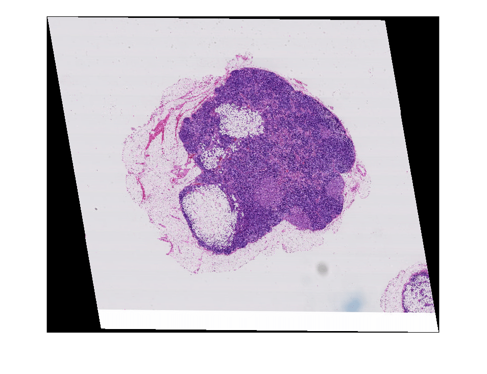
Warp the coarse image by using imwarp. Display the warped image.
imCoarseWarped = imwarp(imCoarse,tform);
imageshow(imCoarseWarped)
Create Spatial Referencing for Warped Fine Image
Before applying the geometric transformation to the image at a fine resolution level, calculate the spatial referencing of the blocked image after the warping. Use this spatial referencing when transforming blocks
Get the pixel extent of the original image from its spatial referencing information.
inPixelExtent = (bim.WorldEnd(1,:)-bim.WorldStart(1,:))./bim.Size(1,:);
Calculate the output horizontal and vertical spatial limits when the transformation is applied.
yWorldLimits = [bim.WorldStart(1,1),bim.WorldEnd(1,1)];
xWorldLimits = [bim.WorldStart(1,2),bim.WorldEnd(1,2)];
[xout,yout] = outputLimits(tform,xWorldLimits,yWorldLimits);
Calculate the size of the output image that preserves the pixel extent. Specify the image size in the format [numrows, numcols].
outImgSize = [ceil(diff(yout)/inPixelExtent(1)), ...
              ceil(diff(xout)/inPixelExtent(2))];
Store the spatial referencing information of the warped image. Set the world limits and image size of the warped image.
outWorldStart = [yout(1) xout(1)];
outWorldEnd = [yout(2) xout(2)];
Calculate the corresponding output pixel dimensions.
outPixelExtent = (outWorldEnd-outWorldStart)./outImgSize;
halfPixelWidth = outPixelExtent/2;
Apply Block-Wise Warping to Fine Image
Create a writable blocked image by specifying the output spatial referencing information. Specify a block size that is large enough to use memory efficiently.
outBlockSize = [1024 1024 3];
bwarped = blockedImage([],[outImgSize 3],outBlockSize,uint8(0), ...
    WorldStart=outWorldStart,WorldEnd=outWorldEnd,Mode="w");
Loop through the output image, one block at a time. For each output block:
Find the coordinates of the four corners of the output block.
Inverse map these coordinates back to the input to get the input (source) region.
Read the contents of the input region.
Create spatial referencing describing the input region.
Calculate the output block content by using
imwarp.Write the output block to the output image by using the
setBlockfunction.
If you have Parallel Computing Toolbox™, then you can replace the outer for statements with parfor statements to run the loops in parallel.
inYWorldLimits = [bim.WorldStart(1,1), bim.WorldEnd(1,1)];
inXWorldLimits = [bim.WorldStart(1,2), bim.WorldEnd(1,2)];

for rBlockInd = 1:bwarped.SizeInBlocks(1)
    for cBlockInd = 1:bwarped.SizeInBlocks(2)

        % Get the indices of the block
        blockSub = [rBlockInd cBlockInd 1];

        % Convert the block indices to pixel subscripts to get the
        % subscript of the top left pixel. Based on the block size,
        % get the subscripts of the bottom right pixel
        blockStartSub = blocksub2sub(bwarped,blockSub);
        blockEndSub = blockStartSub + outBlockSize - 1;

        % Convert the pixel indices to world coordinates. The world
        % coordinates indicate the center of the top left and bottom
        % right pixels of the block in world units
        blockStartWorld = sub2world(bwarped,blockStartSub(1:2));
        blockEndWorld = sub2world(bwarped,blockEndSub(1:2));

        % Spatial referencing information for this block (Note: spatial
        % referencing is in x-y order, while blockStart etc are in y-x
        % order).
        outRegionRef = imref2d(fliplr(outBlockSize(1:2)));
        % Expand the region outwards by half a pixel to align with the
        % outer edge of the block
        outRegionRef.YWorldLimits = [blockStartWorld(1)-halfPixelWidth(1),...
                                     blockEndWorld(1)+halfPixelWidth(1)];
        outRegionRef.XWorldLimits = [blockStartWorld(2)-halfPixelWidth(2),...
                                     blockEndWorld(2)+halfPixelWidth(2)];

        % Output bounding box in world coordinates in x-y order
        outbbox = [
            fliplr(blockStartWorld) % top left
            blockStartWorld(2) blockEndWorld(1) % bottom left
            blockEndWorld(2) blockStartWorld(1) % top right
            fliplr(blockEndWorld)   % bottom right
            ];

        % Get corresponding input region. Note: This region need NOT be
        % rectangular if the transformation includes shear
        inRegion = transformPointsInverse(tform,outbbox);

        % Clamp region to image extents
        inRegion(:,2) = max(inRegion(:,2),inYWorldLimits(1));
        inRegion(:,2) = min(inRegion(:,2),inYWorldLimits(2));
        inRegion(:,1) = max(inRegion(:,1),inXWorldLimits(1));
        inRegion(:,1) = min(inRegion(:,1),inXWorldLimits(2));

        % Find the corresponding input bounding box
        inbboxStart = [min(inRegion(:,1)) min(inRegion(:,2))];
        inbboxEnd   = [max(inRegion(:,1)) max(inRegion(:,2))];

        % Move to y-x (row-col) order
        inbboxStart = fliplr(inbboxStart);
        inbboxEnd = fliplr(inbboxEnd);

        % Convert to pixel subscripts
        inbboxStartSub = world2sub(bim,inbboxStart);
        inbboxEndSub = world2sub(bim,inbboxEnd);

        % Read corresponding input region
        inputRegion = getRegion(bim,inbboxStartSub,inbboxEndSub);

        % Get the input region's spatial referencing
        inRegionRef = imref2d(size(inputRegion));

        % Convert the actual region pixel's centers back to world
        % coordinates
        inbboxStart = sub2world(bim,inbboxStartSub);
        inbboxEnd = sub2world(bim,inbboxEndSub);

        % Convert to pixel edges from pixel centers
        inRegionRef.YWorldLimits = [inbboxStart(1)-halfPixelWidth(1),...
                                    inbboxEnd(1)+halfPixelWidth(2)];
        inRegionRef.XWorldLimits = [inbboxStart(2)-halfPixelWidth(1),...
                                    inbboxEnd(2)+halfPixelWidth(2)];

        % Warp this block
        warpedBlock = imwarp(inputRegion,inRegionRef,tform,OutputView=outRegionRef);

        % Set the block data in the output blocked image
        setBlock(bwarped,blockSub,warpedBlock);

    end
end
Display the warped image.
bwarped.Mode = "r";
bwarped = makeMultiLevel2D(bwarped,Scales=[1 0.5 0.1]);
imageshow(bwarped)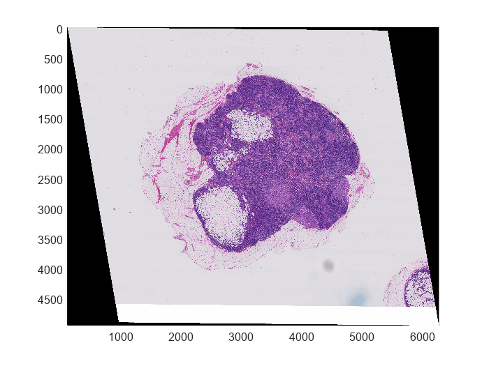
See Also
blockedImage | bigimageshow | setBlock | affinetform2d | imref2d | transformPointsInverse | getRegion