From Video Device
Capture live image data from image acquisition device
Libraries:
Image Acquisition Toolbox
Description
The From Video Device block lets you capture image and video data streams from image acquisition devices, such as cameras and frame grabbers, in order to bring the image data into a Simulink® model. The block also lets you configure and preview the acquisition directly from Simulink.
The From Video Device block opens, initializes, configures, and controls an acquisition device. The block opens, initializes, and configures only once, at the start of the model execution. While the Read All Frames option is selected, the block queues incoming image frames in a FIFO (first in, first out) buffer and delivers one image frame for each simulation time step. If the buffer underflows, the block waits for up to 10 seconds until a new frame is in the buffer.
The block has no input ports. You can configure the block to have either one output port or three output ports corresponding to the uncompressed color bands red, green, and blue or Y, Cb, and Cr. For more information about configuring the output ports, see the Output section.
For an example of how to use this block, see Save Video Data to a File.
Other Supported Features
The From Video Device block supports the use of Simulink Accelerator mode. This feature speeds up the execution of Simulink models.
The From Video Device block supports the use of model referencing. This feature lets your model include other Simulink models as modular components.
The From Video Device block supports the use of Code Generation along with the
packNGo
function to group required source code and dependent shared libraries.
Examples
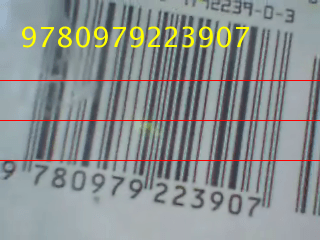
Barcode Recognition Using Live Video Acquisition
Use the From Video Device block to recognize a barcode.
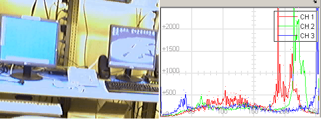
Live Image Acquisition and Histogram Display
Use Simulink® blocks to display live video stream and a histogram of its RGB values side by side.
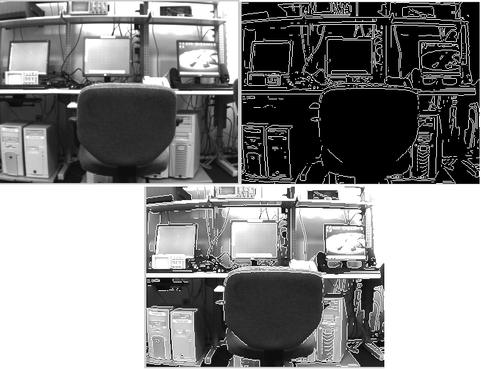
Edge Detection on Live Video Stream
Use the From Video Device block to detect the edges of objects in a live video stream.
Ports
Output
Port_1 — Video output signal
m-by-n-by-3 matrix
Video output signal, specified as an m-by-n-by-3 matrix, where m represents the height of the video image and n represents the width of the video image.
Dependencies
To enable this port, set Ports mode to
One multidimensional signal
.To specify the output video signal data type for this port, set Data type.
Data Types: single
| double
| int8
| uint8
| int16
| uint16
| int32
| uint32
R, G, B — RGB video output signal
m-by-n matrix
RGB video output signal, specified as an m-by-n matrix, where m represents the height of the video image and n represents the width of the video image. R, G, and B are separate output ports that each have the same dimensions.
Dependencies
To enable this port, set Output color space to
rgb
and Ports mode toSeparate color signals
.To specify the output video signal data type for this port, set Data type.
Data Types: single
| double
| int8
| uint8
| int16
| uint16
| int32
| uint32
Y, Cb, Cr — YCbCr video output signal
m-by-n matrix
YCbCr video output signal, specified as an m-by-n matrix, where m represents the height of the video image and n represents the width of the video image. Y, Cb, and Cr are separate output ports that each have the same dimensions.
Dependencies
To enable this port, set Output color space to
YCbCr
and Ports mode toSeparate color signals
.To specify the output video signal data type for this port, set Data type.
Data Types: single
| double
| int8
| uint8
| int16
| uint16
| int32
| uint32
Parameters
The following fields appear in the Block Parameters dialog box. If your selected device does not support a feature, it will not appear in the dialog box.
Device — Image acquisition device
available devices
The image acquisition device to which you want to connect. The items in the list vary, depending on which devices you have connected to your system. All video capture devices supported by Image Acquisition Toolbox™ software are supported by the block.
Video format — Video formats supported by device
available video formats
Shows the video formats supported by the selected device. This list varies with each
device. If your device supports the use of camera files, From camera
file
is one of the choices in the list.
Dependencies
To enable the Camera file parameter, set Video format to
From camera file
. This option only appears if your selected device supports camera raw image files. Enter the camera file path and file name, or use the Browse button to locate it.
Video source — Video input sources supported by device
available video input sources
Available input sources for the specified device and format. Click the Edit properties... button to open the Property Inspector and edit the source properties.
Edit properties... — Video source properties
button
Open the Property Inspector to edit video source device-specific properties, such as brightness and contrast. The properties that are listed vary by device. Properties that can be edited are indicated by a pencil icon or a drop-down list in the table. Properties that are grayed out cannot be edited. When you close the Property Inspector, your edits are saved.
Enable hardware triggering — Hardware-triggered acquisition
off
(default) | on
This option only appears if the selected device supports hardware triggering. Select the check box to enable hardware triggering. After you enable triggering, you can select the Trigger configuration.
Dependencies
To enable the Trigger configuration parameter, select the Enable hardware triggering parameter. This option only appears if the selected device supports hardware triggering. The configuration choices are listed by trigger source/trigger condition. For example,
TTL/fallingEdge
means that TTL is the trigger source and the falling edge of the signal is the condition that triggers the hardware.
ROI position — Region of interest in video image
[0, 0, maximum height, maximum width] (default) | [row, column, height, width]
Use this field to input a row vector that specifies the region of acquisition in the video image. The format is [row, column, height, width]. The default values for row and column are 0. The default values for height and width are set to the maximum allowable value, indicated by the resolution of the video format. Change the values in this field only if you do not want to capture the full image size.
Output color space — Video output color space
rgb
(default) | grayscale
| YCbCr
| bayer
Use this field to select the color space for devices that support color. If your
device supports Bayer sensor alignment, bayer
is also
available.
Dependencies
To enable the Bayer sensor alignment parameter, set Output color space to
bayer
. This option is only available if your device supports Bayer sensor alignment. Use this to set the 2-by-2 pixel alignment of the Bayer sensor. Possible sensor alignment options aregrbg
(default),gbrg
,rggb
, andbggr
.
Preview... — Preview of live video data
button
Preview the video image. Clicking this button opens the Video Preview window. While preview is running the image adjusts to changes you make in the parameter dialog box. Use the Video Preview window to set up your image acquisition in the way you want it to be acquired by the block when you run the model.
Block sample time — Block sampling rate
1/30 (default) | numeric
Specify the sample time of the block during the simulation. The sample time is the rate at which the block is executed during simulation.
Note
The block sample time does not set the frame rate on the device that is used in simulation. The frame rate is determined by the video format specified (standard format or from a camera file). Some devices even list frame rate as a device-specific source property. Frame rate is not related to the Block sample time option in the dialog. The block sample time defines the rate at which the block executes during simulation time.
Ports mode — Type of video output signal
One multidimensional signal
| Separate color signals
This option appears only if your device supports using either one output port or
multiple output ports for the color bands. Use this option to specify either a single
output port for all color spaces, or one port for each band (for example, R, G, and B).
When you select One multidimensional signal
, the output
signal is combined into one line consisting of signal information for all color signals.
Select Separate color signals
if you want to use three ports
corresponding to the uncompressed red, green, and blue color bands. Note that some
devices use YCbCr for the separate color signals.
Note
The block acquires data in the default ReturnedColorSpace
setting for the specified device and format.
Data type — Video output data type
single
(default) | double
| int8
| uint8
| int16
| uint16
| int32
| uint32
The image data type when the block outputs frames. This data type indicates how image frames are returned from the block to Simulink. This option supports all MATLAB® numeric data types.
Read All Frames — All available image frames captured
off
(default) | on
Select to capture all available image frames. If you do not select this option, the
block takes the latest snapshot of one frame, which is equivalent to using the
getsnapshot
function in the toolbox. If you select this option, the
block queues incoming image frames in a FIFO (first in, first out) buffer. The block
still gives you one frame, the oldest from the buffer, every timestep and ensures that
no frames are lost. This option is equivalent to using the getdata
function in the toolbox.
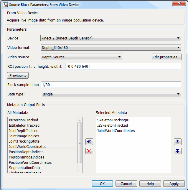
Metadata Output Ports — Kinect® for Windows® output ports
This option only appears if:
You use a Kinect for Windows camera
You select
Kinect Depth Sensor
as Device, andYou select
Depth Source
as Video source.
Use this option to return skeleton information in Simulink during simulation and code generation. You can output metadata information in normal, accelerator, and deployed simulation modes. Each metadata item in the Selected Metadata list becomes an output port on the block.
The All Metadata section lists the metadata that is associated with the Kinect depth sensor.
This section is only visible when a Kinect depth sensor is selected. The All Metadata list shows the available metadata. The Selected Metadata list shows which metadata items are returned to Simulink. This is empty by default. To use a metadata item, add it from the All Metadata to the Selected Metadata list by selecting it in the All Metadata list and clicking the Add button (blue arrow icon). The Remove button (red X icon) removes an item from the Selected Metadata list. You can also use the Move up and Move down buttons to change the order of items in the Selected Metadata list. You can select multiple items at once.
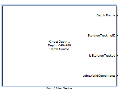
You can see in the example above that three metadata items have been put in the Selected Metadata list. When you click Apply, output ports are created on the block for these metadata, as shown here. The first port is the depth frame.
For descriptions and information on these metadata fields and using Kinect for Windows with the Image Acquisition Toolbox, see Acquire Image and Body Data Using Kinect V2.
Extended Capabilities
C/C++ Code Generation
Generate C and C++ code using Simulink® Coder™.
Usage notes and limitations:
Version History
Introduced in R2007a
MATLAB Command
You clicked a link that corresponds to this MATLAB command:
Run the command by entering it in the MATLAB Command Window. Web browsers do not support MATLAB commands.
Select a Web Site
Choose a web site to get translated content where available and see local events and offers. Based on your location, we recommend that you select: .
You can also select a web site from the following list
How to Get Best Site Performance
Select the China site (in Chinese or English) for best site performance. Other MathWorks country sites are not optimized for visits from your location.
Americas
- América Latina (Español)
- Canada (English)
- United States (English)
Europe
- Belgium (English)
- Denmark (English)
- Deutschland (Deutsch)
- España (Español)
- Finland (English)
- France (Français)
- Ireland (English)
- Italia (Italiano)
- Luxembourg (English)
- Netherlands (English)
- Norway (English)
- Österreich (Deutsch)
- Portugal (English)
- Sweden (English)
- Switzerland
- United Kingdom (English)
Asia Pacific
- Australia (English)
- India (English)
- New Zealand (English)
- 中国
- 日本Japanese (日本語)
- 한국Korean (한국어)