Coordinate Systems in Lidar Toolbox
A lidar sensor uses laser light to construct a 3-D scan of its environment. By emitting laser pulses into the surrounding environment and capturing the reflected pulses, the sensor can use the time-of-flight principle to measure its distance from objects in the environment. The sensor stores this information as a point cloud, which is a collection of 3-D points in space.
Lidar sensors record point cloud data with respect to either a local coordinate system, such as the coordinate system of the sensor or the ego vehicle, or in the world coordinate system.
World Coordinate System
The world coordinate system is a fixed universal frame of reference for all the vehicles, sensors, and objects in a scene. In a multisensor system, each sensor captures data in its own coordinate system. You can use the world coordinate system as a reference to transform data from different sensors into a single coordinate system.
Lidar Toolbox™ uses the right-handed Cartesian world coordinate system defined in ISO 8855, where the x-axis is positive in the direction of ego vehicle movement, the y-axis is positive to the left with regard to ego vehicle movement, and the z-axis is positive going up from the ground.
Sensor Coordinate System
A sensor coordinate system is one local to a specific sensor, such as a lidar sensor or a camera, with its origin located at the center of the sensor.
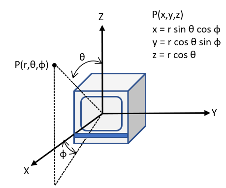
A lidar sensor typically measures the distance of objects from the sensor and collects the information as points. Each point has spherical coordinates of the form (r, Θ, Φ), which you can use to calculate the xyz-coordinates of a point. The orientation of the x-, y-, z- axis of the sensor coordinate system depends on the sensor manufacturer.

r is the distance of the point from the origin
Φ is the azimuth angle in the XY-plane measured from the positive x-axis
Θ is the elevation angle in the YZ-plane measured from positive z-axis
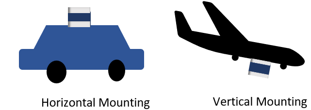
The mounting position and orientation of a lidar sensor can vary depending on its intended application.

Horizontal mounting used on ground vehicles for autonomous driving applications, enables the sensor to scan and detect objects and terrain in its immediate vicinity for applications such as obstacle avoidance.
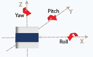
Vertical mounting which is used on aerial vehicles, enables the sensor to scan large landscapes such as forests, plains, and bodies of water. Vertical mounting requires these additional parameters to define the sensor orientation.
Roll — Angle of rotation around the front-to-back axis, which is the x-axis of the sensor coordinate system.
Pitch — Angle of rotation around the side-to-side axis, which is the y-axis of the sensor coordinate system.
Yaw — Angle of rotation around the vertical axis, which is the z-axis of the sensor coordinate system.

Coordinate System Transformation
Applications such as autonomous driving, mining, and underwater navigation use multisensor systems for a more complete understanding of the surrounding environment. Because each sensor captures data in its respective coordinate system, to fuse data from the different sensors in such a setup, you must define a reference coordinate frame and transform the data from all the sensors into reference frame coordinates.
For example, you can select the coordinate system of a lidar sensor as your reference frame. To create reference frame coordinates from your lidar sensor data, you must transform that data by multiplying it with the extrinsic parameters of the lidar sensor.
To apply transformation, you must multiply your data with the extrinsic parameters of the lidar sensor. The extrinsic parameter matrix consists of the translation vector and rotation matrix. The translation vector translates the origin of your selected reference frame to the origin of the world frame, and the rotation matrix rotates the axes to the correct orientation.
Lidar sensors and cameras are often used together to generate accurate 3-D scans of a scene. For more information about lidar-camera data fusion, see What Is Lidar-Camera Calibration?