Main Content

ltePSBCHIndices

PSBCH resource element indices

Description

example

ind = ltePSBCHIndices(ue) returns a column vector of physical sidelink broadcast channel (PSBCH) resource element (RE) indices for the specified UE settings structure. By default, the indices are returned in one-based linear indexing form. You can use this form to directly index elements of a matrix representing the subframe resource grid for antenna port 1010. For more information, see Physical Sidelink Broadcast Channel Indexing.

ind = ltePSBCHIndices(ue,opts) formats the returned indices using options specified by opts.

Examples

collapse all

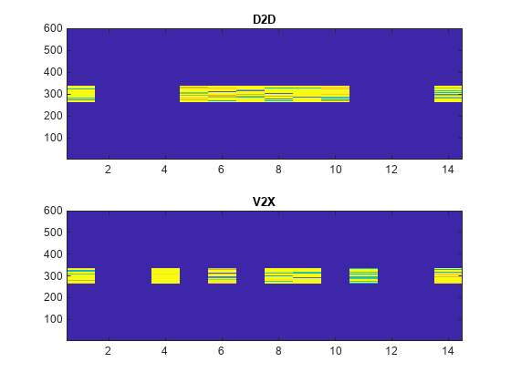
Generate PSBCH values and indices. Write the values into the PSBCH resource elements in a synchronization subframe for both D2D and V2X sidelink modes, and display an image of their locations. This mapping also writes the PSBCH values into the last SC-FDMA guard symbol within a subframe. The sidelink SC-FDMA modulator removes PSBCH values from the last SC-FDMA guard symbol in a separate processing step.

Create a user equipment settings structure and a resource grid that has 10 MHz bandwidth and normal cyclic prefix for D2D sidelink mode.

ue.NSLRB = 50;
ue.CyclicPrefixSL = 'Normal';
ue.NSLID = 1;

Generate an empty resource grid and PSBCH indices. Load the PSBCH indices into the resource grid.

grid_D2D = lteSLResourceGrid(ue);
psbch_indices = ltePSBCHIndices(ue);
grid_D2D(psbch_indices) = ltePSBCH(ue,zeros(2*576,1));

Change user equipment settings to V2X sidelink mode.

ue.SidelinkMode = 'V2X';

Generate an empty resource grid and PSBCH indices. Load the PSBCH indices into the resource grid.

grid_V2X = lteSLResourceGrid(ue);
psbch_indices = ltePSBCHIndices(ue);
grid_V2X(psbch_indices) = ltePSBCH(ue,zeros(2*504,1));

Display the locations of the PSBCH indices for both sidelink modes.

subplot(2,1,1);
image(400*abs(grid_D2D)); 
axis xy; title('D2D');
subplot(2,1,2);
image(400*abs(grid_V2X)); 
axis xy; title(ue.SidelinkMode);

Generate PSBCH indices using zero-based indexing style. Compare these indices to one-based indices.

Create a user equipment settings structure with 10 MHz bandwidth and normal cyclic prefix.

ue.NSLRB = 50;
ue.CyclicPrefixSL = 'Normal';
ue.NSLID = 1;

Generate PSBCH zero-based indices. View the first five indices.

psbch_indices = ltePSBCHIndices(ue,'0based');
psbch_indices_size = size(psbch_indices)
psbch_indices_size = 1×2

   576     1

psbch_indices(1:5)
ans = 5x1 uint32 column vector

   264
   265
   266
   267
   268

Generate PSBCH one-based indices and view the first five indices.

psbch_indices = ltePSBCHIndices(ue,'1based');
psbch_indices_size = size(psbch_indices)
psbch_indices_size = 1×2

   576     1

psbch_indices(1:5)
ans = 5x1 uint32 column vector

   265
   266
   267
   268
   269

For zero-based indexing, the first assigned index is one lower than the one-based indexing style.

Input Arguments

collapse all

User equipment settings, specified as a parameter structure containing these fields:

Sidelink mode, specified as 'D2D' or 'V2X'.

Data Types: char | string

Number of sidelink resource blocks, specified as an integer scalar from 6 to 110.

Example: 6, which corresponds to a channel bandwidth of 1.4 MHz.

Data Types: double

Cyclic prefix length, specified as 'Normal' or 'Extended'.

Data Types: char | string

Output format options for resource element indices, specified as a character vector, cell array of character vectors, or string array. For convenience, you can specify several options as a single character vector or string scalar by a space-separated list of values placed inside the quotes. Values for opts when specified as a character vector include (use double quotes for string) :

Category Options Description

Indexing style

'ind' (default)

The returned indices are in linear index style.

'sub'

The returned indices are in [subcarrier,symbol,port] subscript row style.

Index base

'1based' (default)

The returned indices are one-based.

'0based'

The returned indices are zero-based.

Example: 'ind 1based', "ind 1based", {'ind','1based'}, or ["ind","1based"] specify the same formatting options.

Data Types: char | string | cell

Output Arguments

collapse all

PSBCH resource element indices, returned as an integer column vector or a three-column integer matrix. By default, the returned vector or matrix has 576 PSBCH resource element indices for normal cyclic prefix or 432 PSBCH resource element indices for extended cyclic prefix. For the V2X sidelink mode, there are 504 PSBCH resource element indices. For more information, see Physical Sidelink Broadcast Channel Indexing.

Data Types: uint32

More About

collapse all

Physical Sidelink Broadcast Channel Indexing

Use the ltePSBCHIndices indexing function and the corresponding ltePSBCH sequence function to populate the resource grid for the desired synchronization subframe number. The indices are ordered as the PSBCH QPSK modulation symbols should be mapped, applying frequency-first mapping, and include indices for the last SC-FDMA guard symbol. The PSBCH values returned by ltePSBCH are ordered as they should be mapped into the resource elements of the adjacent symbols using ltePSBCHIndices. For more information on mapping symbols to the resource element grid, see Resource Grid Indexing.

Physical Sidelink Broadcast Channel

The physical sidelink broadcast channel (PSBCH) is transmitted in the central 72 resource elements in the available SC-FDMA symbols of synchronization subframes. For D2D sidelink mode, the available symbols exclude the three symbols per slot assigned to the PSBCH DRS and sidelink synchronization signals. For V2X sidelink, a total of seven symbols will be excluded in a subframe (three symbols for PSBCH DRS and 4 for the PSSS/SSSS). The resource elements in the last SC-FDMA symbol within a subframe are counted in the mapping process. Before transmission, the PSBCH resource elements are removed from the last SC-FDMA symbol by lteSCFDMAModulate during the sidelink-specific SC-FDMA modulation and guard symbol creation.

If a terminal is transmitting a synchronization subframe, then it should be sent every 40 ms for D2D sidelink mode or every 160 ms for V2X, with the exact subframe dependent on the RRC-signaled subframe number offset (syncOffsetIndicator-r12). The subframe also contains values for the ltePSBCHDRSIndices on port 1010 and ltePSSSIndices and lteSSSSIndices on port 1020. No PSCCH or PSSCH transmission will occur in a sidelink subframe configured for synchronization purposes.

Version History

Introduced in R2016b