lteSLFrameOffsetPSBCH
PSBCH DM-RS sidelink subframe timing estimate
Description
offset = lteSLFrameOffsetPSBCH(ue,waveform)waveform,
given UE-specific settings, ue.
The returned offset indicates the number
of samples from the start of the input waveform to the position in
that waveform where the first subframe containing the DM-RS begins.
Examples
Synchronize and demodulate a transmission that has been delayed by five samples. The transmission contains PSBCH demodulation reference signal (DM-RS) symbols that are used when estimating the waveform timing offset.
Create a UE configuration specifying 15 resource blocks, a sidelink identity of 1, and a normal cyclic prefix.
ue = struct('NSLRB',15,'NSLID',1,'CyclicPrefixSL','Normal');
Create a resource grid and modulate the waveform containing PSBCH DM-RS symbols.
txgrid = lteSLResourceGrid(ue);
txgrid(ltePSBCHDRSIndices(ue)) = ltePSBCHDRS(ue);
txwaveform = lteSLSCFDMAModulate(ue,txgrid);
Add a time delay of five samples.
rxwaveform = [zeros(5,1); txwaveform];
Calculate the timing offset in samples.
offset = lteSLFrameOffsetPSBCH(ue,rxwaveform)
offset =
5
Correct the timing offset and demodulate the received waveform.
rxGrid = lteSLSCFDMADemodulate(ue,rxwaveform(1+offset:end));
View the correlation peak for a transmission waveform that has been delayed by five samples. The transmission contains PSBCH demodulation reference signal (DM-RS) symbols available for estimating the waveform timing.
Create a UE configuration specifying 15 resource blocks, a sidelink identity of 1, and a normal cyclic prefix.
ue = struct('NSLRB',15,'NSLID',1,'CyclicPrefixSL','Normal');
Create a resource grid and modulate the waveform containing PSBCH DM-RS symbols.
txgrid = lteSLResourceGrid(ue);
txgrid(ltePSBCHDRSIndices(ue)) = ltePSBCHDRS(ue);
txwaveform = lteSLSCFDMAModulate(ue,txgrid);
Calculate the timing offset in samples.
[offset corr] = lteSLFrameOffsetPSBCH(ue,txwaveform);
Add a time delay of five samples.
rxwaveform = [zeros(5,1); txwaveform];
Calculate the timing offset in samples.
[offset corrDelayed] = lteSLFrameOffsetPSBCH(ue,rxwaveform);
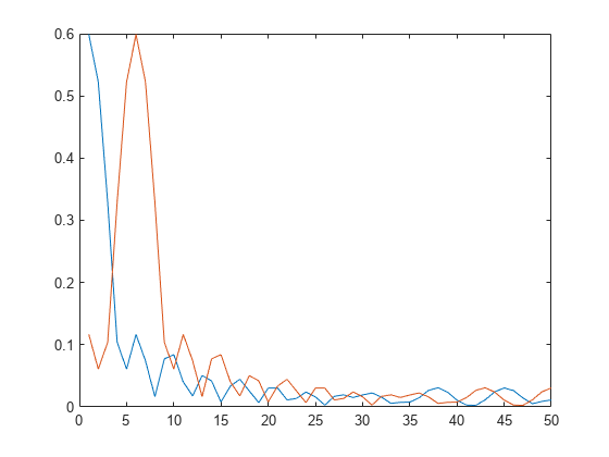
Plot the correlation data before and after delay is added. Zoom in on the x-axis to view correlation peaks.
plot(corr)
hold on
plot(corrDelayed)
hold off
xlim([0 50])
Correct the timing offset and demodulate the received waveform.
rxGrid = lteSLSCFDMADemodulate(ue,rxwaveform(1+offset:end));
Input Arguments
Output Arguments
Version History
Introduced in R2017a