Waveform Acquisition and Analysis using LTE Toolbox with Test and Measurement Equipment
This example shows how an over-the-air LTE waveform can be captured and analyzed using the LTE Toolbox™, the Instrument Control Toolbox™ and RF signal analyzer hardware.
Introduction
The LTE Toolbox can be used to perform both standard compliant and custom decoding and analysis of baseband LTE signals. Using the LTE Toolbox with the Instrument Control Toolbox allows waveforms to be captured using test and measurement hardware and be taken into MATLAB® for visualization, analysis and decoding.
In this example, the Instrument Control Toolbox is used to capture an over-the-air LTE signal using a Keysight Technologies® N9010A signal analyzer and retrieve it into MATLAB for analysis. The over-the-air signal is generated using a Keysight Technologies N5172B signal generator.

In this example, the captured waveform is analyzed by performing two measurements using the LTE Toolbox:
Adjacent Channel Leakage Power Ratio: ACLR is used as a measure of the amount of power leaking into adjacent channels and is defined as the ratio of the filtered mean power centered on the assigned channel frequency to the filtered mean power centered on an adjacent channel frequency. See LTE Downlink Adjacent Channel Leakage Power Ratio (ACLR) Measurement for a more detailed explanation.
PDSCH Error Vector Magnitude: EVM is a measure of the difference between the ideal symbols and the measured symbols after the equalization. See PDSCH Error Vector Magnitude (EVM) Measurement for a more detailed explanation.
Generate the Over-the-Air Signal
The LTE Toolbox can be used to generate standard or custom baseband IQ waveforms. Waveform Generation and Transmission Using LTE Toolbox with Test and Measurement Equipment demonstrates how to generate an over-the-air LTE waveform using the LTE Toolbox and a Keysight Technologies signal generator.
In this example, Keysight Technologies N7624B Signal Studio and an N5172B signal generator are used to generate a standard-compliant RF LTE downlink waveform at a 1GHz center frequency. Note 1GHz is selected as an example frequency and is not intended to be a recognized LTE channel.
A 40ms 5MHz FDD R.6 Reference Measurement Channel (RMC) waveform is generated and looped for capture. The HARQ retransmissions are turned off to simplify synchronization at the receiver and the OCNG is enabled to fill unused resource elements to keep signal power constant.
LTE Signal Parameters
To analyze the received waveform a number of system parameters must be known. As a standard RMC waveform is captured lteRMCDL is used to generate a configuration structure for RMC R.6. This provides the parameters required for analysis, such as the signal bandwidth, downlink control configuration and resource allocation. Alternatively, these parameters can be obtained through blind decoding as demonstrated in Cell Search, MIB and SIB1 Recovery.
% RMC configuration
rmc = lteRMCDL('R.6');
% Ensure that the HARQ retransmissions are turned off at the transmitter so
% that the Redundancy Version (RV) is the same in every subframe. This
% simplifies synchronization as the receiver does not need to take account
% of an RV pattern that spans multiple frames.
rmc.PDSCH.RVSeq = 0; % Single transmission of the transport block
% Enable OCNG fill
rmc.OCNGPDSCHEnable = 'On';
rmc.OCNGPDCCHEnable = 'On';

% Write the sampling rate and UTRA chip rate to the configuration structure
% to allow the calculation of ACLR parameters
info = lteOFDMInfo(rmc);
rmc.SamplingRate = info.SamplingRate;
% UTRA chip rate in MCPS
rmc.UTRAChipRate = 3.84;
Calculate ACLR Parameters
The parameters required for ACLR measurement are calculated using the helper function hACLRParameters.m.
Determine measurement bandwidth - The measurement bandwidth range should cover the two E-UTRA adjacent channels of the same bandwidth as the signal and the two 5MHz UTRA channels as given by TS 36.104 Table 6.6.2.1-1
Determine UTRA Parameters - The UTRA chip rates and bandwidths
% Calculate ACLR measurement parameters
[aclr, nRC, R_C, BWUTRA] = hACLRParameters(rmc);
Acquire the Baseband Signal in MATLAB from a Signal Analyzer
To analyze the over-the-air transmission in MATLAB, the Instrument Control Toolbox is used to configure the Keysight Technologies N9010A signal analyzer and capture baseband IQ data. The helper function hCaptureIQUsingN9010A.m retrieves the baseband IQ data and the capture sampling rate from the signal analyzer, ready for analysis in MATLAB. Note that 40 subframes are captured for analysis.
capSubframes = 40;      % Number of subframes to capture
centerFrequency = 1e9;  % 1GHz center frequency

% The frequency range should cover the two E-UTRA adjacent channels of the
% same bandwidth as the signal and the two 5MHz UTRA channels
startFreq = centerFrequency-aclr.BandwidthACLR/2;
stopFreq = centerFrequency+aclr.BandwidthACLR/2;
externalTrigger = false;
capTime = capSubframes*1e-3; % 1 subframes is 1ms
resBW = 91e3;
videoBW = 91e3;
[captureWaveform,captureSampleRate] = hCaptureIQUsingN9010A( ...
    'A-N9010A-21026.dhcp.mathworks.com',capTime, ...
    centerFrequency,stopFreq-startFreq,externalTrigger,startFreq,stopFreq, ...
    resBW,videoBW);

rxWaveform = captureWaveform(1:end-1);
captureSampleRate = round(captureSampleRate);
Plot Received Signal Spectrum
Inspect the function hCaptureIQUsingN9010A.m for more details on input parameters and the commands needed to configure the Keysight Technologies N9010A signal analyzer and retrieve the data.
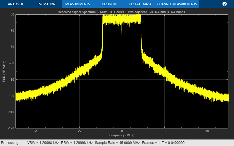
Plotting the frequency spectrum of the retrieved time domain baseband waveform using the DSP System Toolbox™ spectrumAnalyzer object shows the expected LTE 5 MHz occupied bandwidth and adjacent bands required for ACLR measurement, with impairments due to RF transmission and reception.
spectrumPlotRx = spectrumAnalyzer;
spectrumPlotRx.Method = 'welch';
spectrumPlotRx.SampleRate =  captureSampleRate;
spectrumPlotRx.SpectrumType = 'power-density';
spectrumPlotRx.SpectrumUnits =  'dBm';
spectrumPlotRx.RBWSource = 'property';
spectrumPlotRx.RBW = 1.3e3;
spectrumPlotRx.FrequencySpan = 'span-and-center-frequency';
spectrumPlotRx.Span = aclr.BandwidthACLR;
spectrumPlotRx.CenterFrequency = 0;
spectrumPlotRx.Window = 'rectangular';
spectrumPlotRx.YLimits = [-120 -50];
spectrumPlotRx.YLabel = 'PSD';
spectrumPlotRx.ShowLegend = false;
spectrumPlotRx.Title = 'Received Signal Spectrum: 5 MHz LTE Carrier + Two adjacent E-UTRA and UTRA bands ';
spectrumPlotRx(rxWaveform);
Adjacent Carrier Leakage Ratio Measurement
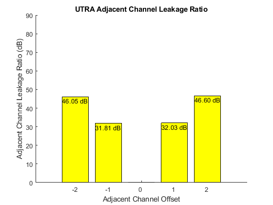
The E-UTRA and UTRA ACLR of the captured waveform are measured using the helper functions hACLRMeasurementEUTRA.m and hACLRMeasurementUTRA.m. The example LTE Downlink Adjacent Channel Leakage Power Ratio (ACLR) Measurement describes E-UTRA and UTRA measurements in more detail. The filter used in the transmitter affects the ACLR performance, so by optimizing the transmit side filter, improvements can be made to the ACLR.
% Apply required resampling for ACLR calculation. The capture sampling rate
% must be greater than the ACLR sampling rate for correct measurement
if captureSampleRate < aclr.SamplingRate
    warning(['The capture sampling rate (%d) is less than the minimum sampling ' ...
        'rate required for ACLR measurement (%d), ACLR may be inaccurate!'],captureSampleRate,aclr.SamplingRate);
end
resampled = resample(rxWaveform,aclr.SamplingRate,captureSampleRate);

% Measure E-UTRA and UTRA ACLR
aclr = hACLRMeasurementEUTRA(aclr,resampled);
aclr = hACLRMeasurementUTRA(aclr,resampled,nRC,R_C,BWUTRA);

% Plot ACLR results
fprintf('\nACLR Analysis:\n');
hACLRResults(aclr);
ACLR Analysis:
          Bandwidth: 5000000
    BandwidthConfig: 4500000
      BandwidthACLR: 25000000
                OSR: 4
       SamplingRate: 30720000
    EUTRACenterFreq: [-10000000 -5000000 5000000 10000000]
      EUTRAPowerdBm: 13.9473
            EUTRAdB: [45.6010 31.1040 31.1841 46.0544]
       UTRAPowerdBm: 13.3327
             UTRAdB: [46.0508 31.8147 32.0256 46.6009]
     UTRACenterFreq: [-10000000 -5000000 5000000 10000000]


Prepare the Captured LTE Signal for EVM Analysis
The waveform used above for ACLR measurement also contains adjacent bands which are not required for EVM measurement. So the waveform is resampled to the sample rate of the OFDM modulator which will be used to demodulate the received signal, and synchronized to the first frame boundary to allow for OFDM demodulation.
rxWaveform = resample(rxWaveform,rmc.SamplingRate,captureSampleRate);

% Synchronize to the first frame head
offset = lteDLFrameOffset(rmc,rxWaveform);
rxWaveform = rxWaveform(1+offset:end,:);

% Extract 2 frames (20ms) for analysis
nFramesAnalyse = 2;
nFramesWaveform = length(rxWaveform)/(info.SamplingRate*10e-3);
rxWaveform = rxWaveform( ...
    1:(info.SamplingRate*(min(nFramesAnalyse,nFramesWaveform)*10e-3)));
PDSCH Error Vector Magnitude Measurement
The average EVM of the received PDSCH symbols is measured using the helper function hPDSCHEVM.m. The example PDSCH Error Vector Magnitude (EVM) Measurement demonstrates a standard compliant EVM measurement as per TS 36.104, Annex E [ 1 ]. Note that the helper function hPDSCHEVM.m can also measure the EVM of Test Model (E-TM) waveforms such as that generated in Waveform Generation and Transmission Using LTE Toolbox with Test and Measurement Equipment.
In this example, the channel estimator is configured to estimate a time and frequency varying channel as an over-the-air signal capture is analyzed. A conservative 9-by-9 pilot averaging window is used, in time and frequency, to reduce the impact of noise on pilot estimates during channel estimation.
cec.PilotAverage = 'UserDefined';
cec.FreqWindow = 9;
cec.TimeWindow = 9;
cec.InterpType = 'cubic';
cec.InterpWinSize = 3;
cec.InterpWindow = 'Causal';
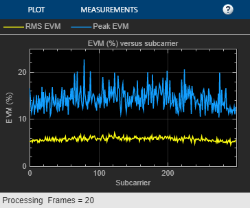
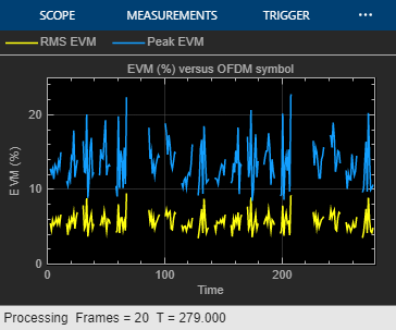
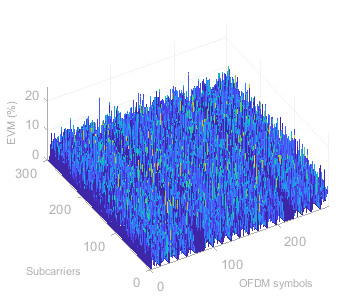
The average EVM for the received waveform is displayed at the command window. A number of plots are also produced:
EVM versus OFDM symbol
EVM versus subcarrier
EVM versus resource block
EVM versus OFDM symbol and subcarrier (i.e. the EVM resource grid)
% Perform EVM measurement
fprintf('\nEVM Analysis:\n');
[evmMeas, evmPlots] = hPDSCHEVM(rmc,cec,rxWaveform);
EVM Analysis:
Low edge EVM, subframe 0: 5.558%
High edge EVM, subframe 0: 5.551%
Low edge EVM, subframe 1: 5.751%
High edge EVM, subframe 1: 5.736%
Low edge EVM, subframe 2: 5.993%
High edge EVM, subframe 2: 5.991%
Low edge EVM, subframe 3: 5.797%
High edge EVM, subframe 3: 5.815%
Low edge EVM, subframe 4: 5.897%
High edge EVM, subframe 4: 5.912%
Low edge EVM, subframe 6: 5.928%
High edge EVM, subframe 6: 5.938%
Low edge EVM, subframe 7: 6.153%
High edge EVM, subframe 7: 6.148%
Low edge EVM, subframe 8: 5.133%
High edge EVM, subframe 8: 5.113%
Low edge EVM, subframe 9: 5.619%
High edge EVM, subframe 9: 5.619%
Averaged low edge EVM, frame 0: 5.769%
Averaged high edge EVM, frame 0: 5.769%
Averaged EVM frame 0: 5.769%
Low edge EVM, subframe 0: 5.517%
High edge EVM, subframe 0: 5.506%
Low edge EVM, subframe 1: 5.632%
High edge EVM, subframe 1: 5.615%
Low edge EVM, subframe 2: 5.883%
High edge EVM, subframe 2: 5.886%
Low edge EVM, subframe 3: 5.821%
High edge EVM, subframe 3: 5.806%
Low edge EVM, subframe 4: 5.892%
High edge EVM, subframe 4: 5.896%
Low edge EVM, subframe 6: 5.894%
High edge EVM, subframe 6: 5.889%
Low edge EVM, subframe 7: 6.100%
High edge EVM, subframe 7: 6.108%
Low edge EVM, subframe 8: 5.183%
High edge EVM, subframe 8: 5.167%
Low edge EVM, subframe 9: 5.574%
High edge EVM, subframe 9: 5.594%
Averaged low edge EVM, frame 1: 5.731%
Averaged high edge EVM, frame 1: 5.728%
Averaged EVM frame 1: 5.731%
Averaged overall EVM: 5.750%

Appendix
This example uses these helper functions:
Selected Bibliography
3GPP TS 36.104 "Base Station (BS) radio transmission and reception"