Motor Control Architectures Based on Different Current Sampling and PWM Frequencies
This example enables you to implement different motor control architectures that use non-identical sampling rates for ADC conversion, PWM, and current controller algorithm to run a permanent magnet synchronous motor (PMSM) using field-oriented control (FOC).
The response of any motor control algorithm depends largely on the ADC sampling frequency as well as PWM switching frequency. ADC sampling rate affects motor current detection as well as position sensing, whereas, PWM frequency impacts output stator voltage actuation.
The example enables you to use the following motor control architectures. Each architecture defines a unique method of implementing the ADC, PWM, and control algorithm.
Synchronized ADC - PWM
ADC oversampling
PWM double update
Faster PWM
PWM dithering
Advance ADC trigger (to compensate for ADC measurement delay)
Single shunt based current measurement
Required MathWorks Products
To simulate model:
Motor Control Blockset™
To generate code and deploy model:
Motor Control Blockset
Embedded Coder®
C2000™ Microcontroller Blockset
Synchronized ADC - PWM
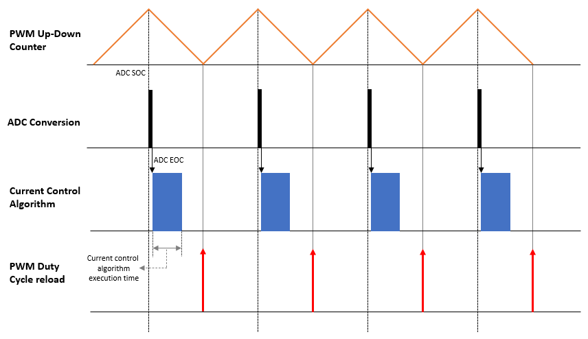
The Synchronized ADC - PWM architecture uses identical frequencies for PWM up-down counter, ADC conversion, and current control algorithm. The architecture keeps ADC conversion and current control algorithm synchronized and keeps both of them aligned with the PWM as shown in the following figure.

As shown in the preceding figure, the architecture triggers ADC (for measuring motor current and position feedback) at the center of each PWM cycle. When the ADC results are available, the control algorithm starts running, which in turn determines the PWM duty cycle for the next PWM cycle.
By default, all Motor Control Blockset™ examples use this architecture.
ADC Oversampling
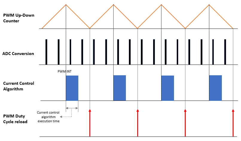
The ADC oversampling architecture uses an ADC conversion frequency that is different from the frequency for PWM up-down counter and current control algorithm. Each PWM cycle has multiple ADC triggers as shown in the following figure.

The control algorithm runs at the same rate as that of the PWM and aligns with center of the PWM cycle. Therefore, the control algorithm starts executing when PWM counter reaches maximum value, and therefore, determines the PWM duty cycle for the next PWM cycle. The algorithm uses averaged results from all ADC conversion instances in the PWM cycle.
These are some advantages of the ADC Oversampling architecture:
Improved resolution - The architecture increases the resolution beyond a limit that the ADC hardware directly supports. Such a resolution helps detect small changes in signals as well as enable you to implement precise control.
Reduced noise - The architecture improves signal-to-nosie ratio in the ADC output.
Software partitioning - This architecture enables you to partition the software for multi-core or multi-processor operation by running ADC conversion, current control algorithm, and PWM counter in parallel.
The architecture has the following limitation:
Requires current measurement in line - If you use this architecture, you cannot use the lower leg of the inverter half-bridge to measure motor current.
Note: Synchronizing current control algorithm with PWM is not always necessary.
Open Live Script
Click ADC Oversampling to access the example live script that instructs you implement the ADC oversampling architecture using simulation and code generation.
PWM Double Update
The PWM double update architecture updates duty cycle twice during each PWM cycle. The example implements double update by setting the ADC conversion (and current control algorithm) frequency as twice the frequency of the PWM up-down counter. Each PWM cycle has two ADC triggers as shown in the following figure.

As shown in the preceding figure, the architecture triggers ADC (for measuring motor current and position feedback) at the beginning as well as at the center of the PWM cycle. The control algorithm starts running when the ADC results are available. Each instance of control algorithm execution determines the PWM duty cycle for the next half of the PWM cycle.
These are some advantages of the PWM double update architecture:
Improved precision - The architecture enables you to make finer adjustments in the speed and position of the motor, which results in a more precise control.
Smoother operation - The architecture can result in a smoother transition between different speed or position levels. The smoother transition occurs because the control algorithm updates the duty cycle twice during one PWM cycle.
Reduced ripple - The architecture can help reduce ripple in the motor current, and therefore, can help you generate smoother torque by reducing noise and vibrations.
These are some limitations of the PWM double update architecture:
Requires current measurement in line - If you use this architecture, you cannot use the lower leg of the inverter half-bridge to measure motor current.
Increased computational load - Implementing PWM double update architecture requires more computational resources compared to single update. This limitation can impact a resource-constrained system.
Note: Current measurement and current control is not mandatory for each half of the PWM cycle. Alternatively, you can use position extrapolation to set the voltage space vector for each alternate PWM update.
Open Live Script
Click PWM Double Update to access the example live script that instructs you implement the PWM double update architecture using simulation and code generation.
Faster PWM
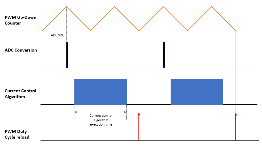
The Faster PWM architecture uses a PWM up-down counter frequency that is twice the frequency of the ADC conversion (and current control algorithm) frequency. An instance of the ADC trigger and control algorithm execution occurs once every two PWM cycles.

These are some advantages of the PWM double update architecture:
Lesser computational load - The architecture enables you to implement high frequency PWM on a less powerful processor.
Lower control frequency support - The architecture enables the control algorithm to run at a lower rate, and therefore, accommodate more execution time.
The architecture has the following limitation:
High switching loss - The architecture can result in higher switching losses because of a higher PWM frequency.
Open Live Script
Click Faster PWM to access the example live script that instructs you implement the Faster PWM architecture using simulation and code generation.
PWM Dithering
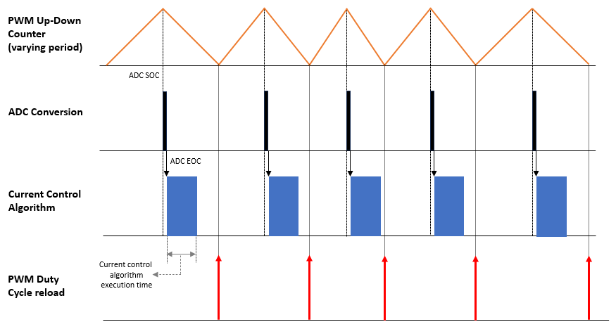
The PWM dithering architecture enables you to vary the PWM up-down counter frequency according to the system requirements as shown in the following figure.

As shown in the preceding figure, the architecture keeps ADC conversion and current control algorithm synchronized and keeps both of them aligned with the PWM. It triggers ADC (for measuring motor current and position feedback) at the center of each PWM cycle. When the ADC results are available, the control algorithm starts running, which in turn determines the PWM duty cycle for the next PWM cycle.
The architecture has the following advantage:
Improve EMC - EMI - You can use this architecture to improve the audible noise in a PWM signal or reduce EMC EMI.
The architecture has the following limitation:
Complex implementation - The varying PWM frequency can be difficult to implement on some processors and hardware.
Note: The execution time of the current control algorithm restricts the amount of variation possbile in the PWM frequency using dithering.
Open Live Script
Click PWM Dithering to access the example live script that instructs you implement the PWM dithering architecture using simulation and code generation.
Advance ADC Trigger (to Compensate for ADC Measurement Delay)
The advance ADC trigger architecture advances the timing of ADC trigger by half the ADC conversion time such that the ADC conversion time is equally divided across the center of the PWM cycle as shown in the following figure.

As shown in the preceding figure, the architecture keeps ADC conversion and current control algorithm synchronized and keeps both of them aligned with the PWM. It triggers ADC (for measuring motor current and position feedback) at the center of each PWM cycle. When the ADC results are available, the control algorithm starts running, which in turn determines the PWM duty cycle for the next PWM cycle.
These are some advantages of the advance ADC trigger architecture:
Increased range for PWM duty cycles - Because the ADC conversion time restricts the minimum achievable duty cycle, the architecture uses a center aligned PWM to align the ADC conversion at the center of the PWM, which extends the minimum possible duty cycle.
Increased execution time for control algorithm - The architecture increases the availability of resources to run the control algorithm by shifting ADC conversion to a non-utilized region.
These are some limitations of the advance ADC trigger architecture:
Complex design - The hardware or microcontroller must support configuration of a compare value other than the value zero or the PWM counter period value.
Precise computation of ADC conversion timer is challenging - Unless the data for ADC conversion is readily available, computing the ADC conversion time precisely can be challenging.
Open Live Script
Click Advance ADC Trigger to access the example live script that instructs you implement the advance ADC trigger architecture using simulation and code generation.
Single-Shunt Current Measurement
The single-shunt current measurement architecture uses single-shunt current reconstruction to derive all necessary current feedback by sampling the currents in the DC link shunt resistor. This architecture eliminates the need to use multiple current sense circuits. You can then use the reconstructed phase currents to perform computations for field-oriented control (FOC) algorithm.

For more details about single shunt current measurement, see Sensorless Field-Oriented Control of PMSM Using DC Shunt Current Sensing.
These are some advantages of the advance ADC trigger architecture:
Cost-effectiveness - Single-shunt current sensing reduces hardware complexity and associated costs. Instead of using multiple shunt resistors, a single shunt resistor estimates the motor current.
Simplified circuitry - Single-shunt measurement uses the same circuit to sense all three phases of the motor current. This architecture simplifies the hardware design and reduces the number of hardware components.
These are some limitations of the advance ADC trigger architecture:
Limited accuracy at low speeds - Single-shunt current sensing can be less accurate at very low speeds. Estimating rotor position and speed can be challenging when the motor operates at near zero speed.
Reduced dynamic performance - Single-shunt based FOC simplifies the hardware, however, it may result in increased torque ripple and reduced dynamic performance, when compared with other more accurate current sensing methods.
Higher torque ripple - Reconstructing three-phase motor currents from a single shunt resistor can introduce torque ripple, which can impact motor operation.