永磁同步电机 (PMSM)
利用参考示例来实现基于传感器和无传感器的电机控制算法,涵盖适用于 PMSM 的传统方法和高级方法。
精选示例

以开环控制方式运行三相 AC 电机并校准 ADC 偏移量
此示例使用开环控制(也称为标量控制或伏特/赫兹控制)来运行电机。这种方法会改变定子电压和频率来控制转子转速,而不使用来自电机的任何反馈。您可以使用这种方法来检查硬件连接的完整性。开环控制的恒速应用使用固定频率的电机电源。开环控制的可调速应用需要可变频率电源来控制转子转速。为了确保恒定的定子磁通,请保持电源电压振幅与其频率成比例。
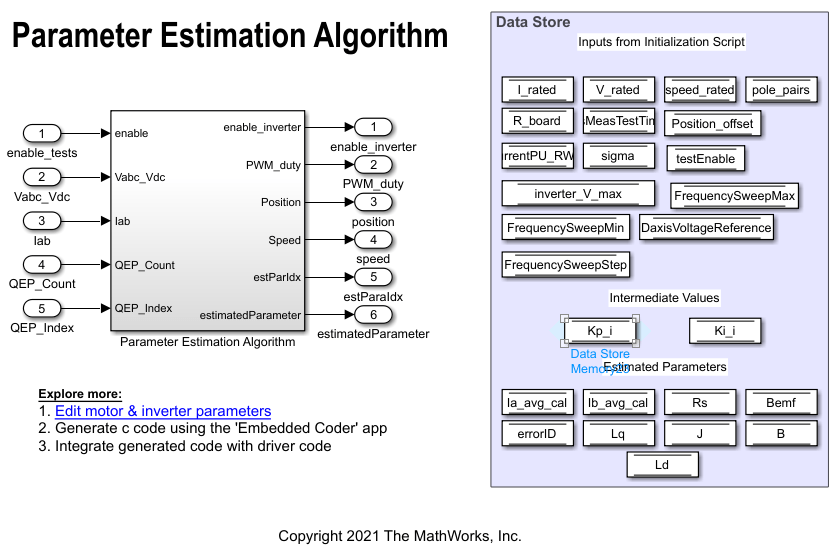
使用自定义硬件估计 PMSM 参数
此示例包括一个算法。自定义电机控制硬件(在 Motor Control Blockset™ 示例中未使用的硬件)通过该算法来确定永磁同步电机 (PMSM) 的参数。算法确定以下参数:
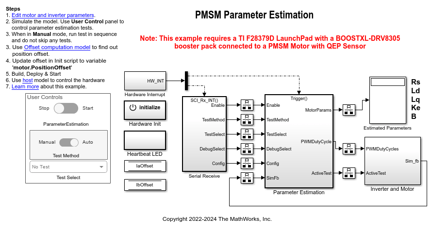
使用参数估计模块估计 PMSM 参数
此示例使用 Motor Control Blockset™ 提供的参数估计模块来估计具有正交编码器的永磁同步电机 (PMSM) 的以下参数:
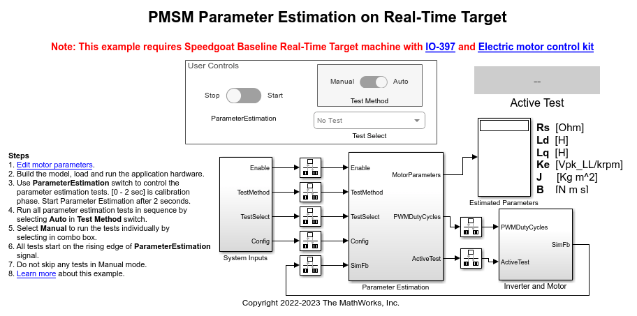
Estimate PMSM Parameters Using Parameter Estimation Blocks on Real-Time Systems
Uses the parameter estimation blocks provided by Motor Control Blockset™ to estimate these parameters of a permanent magnet synchronous motor (PMSM):
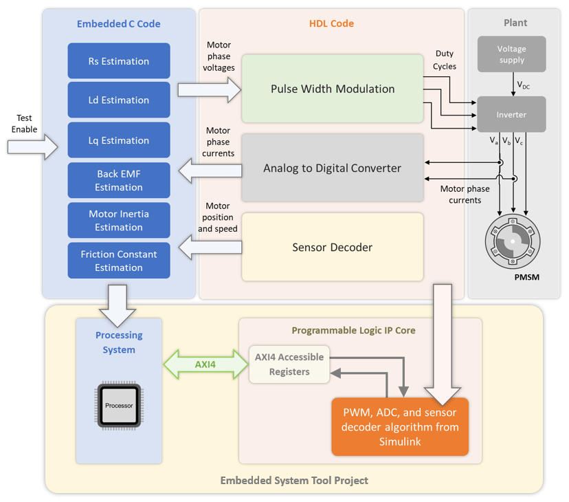
Estimate PMSM Parameters Using FPGA-Based Motor Control Development Kit
Estimate parameters of a permanent magnet synchronous motor (PMSM) using blocks from Motor Control Blockset™ on an FPGA device (Trenz Electronic™ Motor Control Development Kit TE0820).
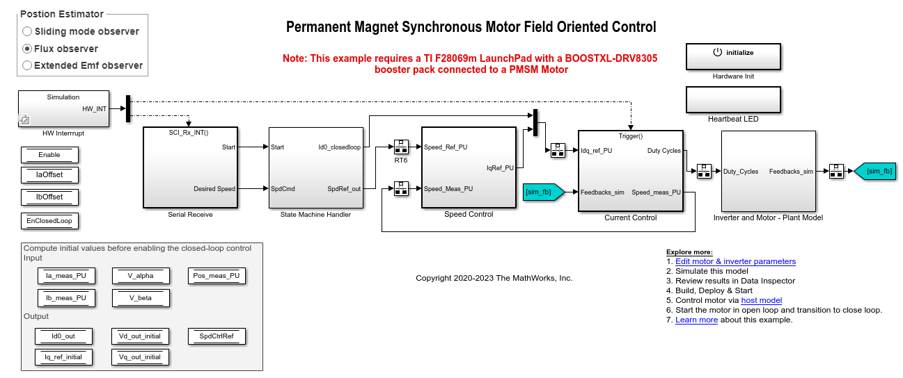
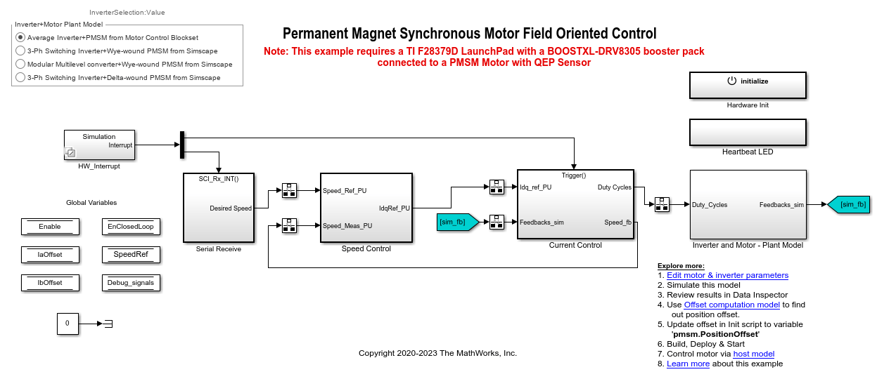
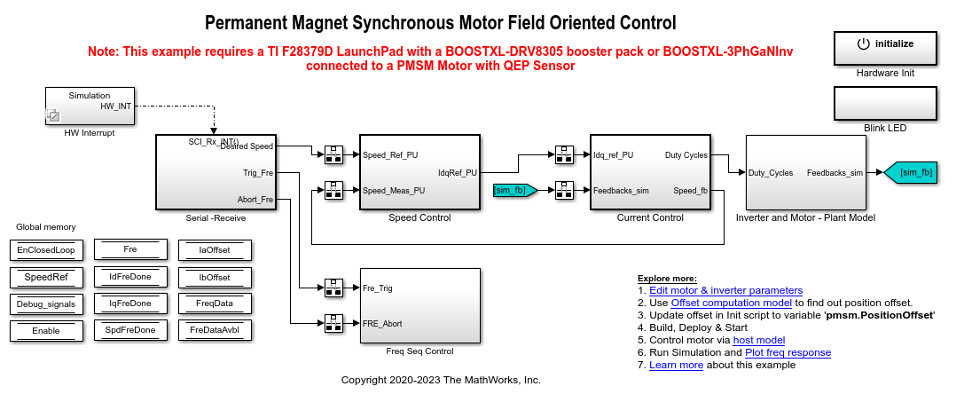
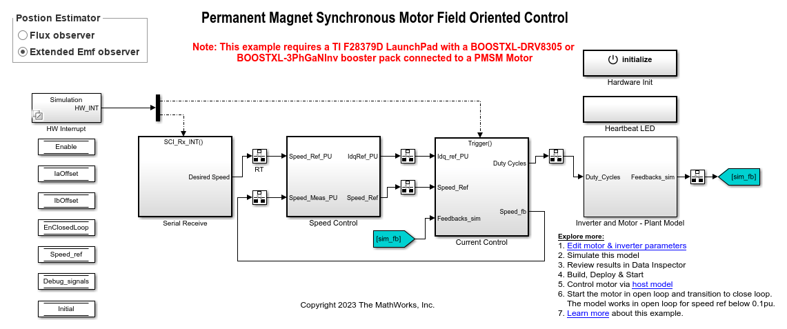
PMSM 的无传感器磁场定向控制
此示例采用磁场定向控制 (FOC) 方法来控制三相永磁同步电机 (PMSM) 的转速。有关 FOC 的详细信息,请参阅磁场定向控制。
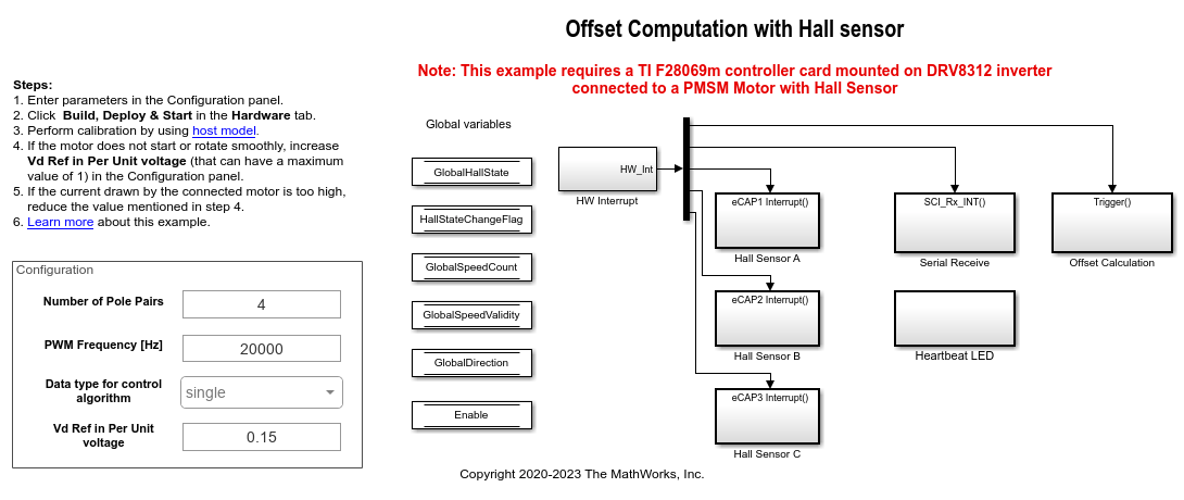
PMSM 的霍尔偏移量校准
此示例计算转子直轴(d 轴)和霍尔传感器检测到的位置之间的偏移量。磁场定向控制 (FOC) 算法需要此位置偏移量来正确运行永磁同步电机 (PMSM)。为了计算偏移量,目标模型在开环条件下运行电机。该模型使用常量 (沿定子
d 轴的电压)和零值 (沿定子
q 轴的电压),通过使用位置或斜坡发生器来运行电机(以低恒定转速)。当位置或斜坡值达到零时,对应的转子位置就是霍尔传感器的偏移值。

使用霍尔传感器的 PMSM 的磁场定向控制
此示例采用磁场定向控制 (FOC) 方法来控制三相永磁同步电机 (PMSM) 的转速。FOC 算法需要转子位置反馈,通过使用霍尔传感器获得该反馈。有关 FOC 的详细信息,请参阅磁场定向控制。
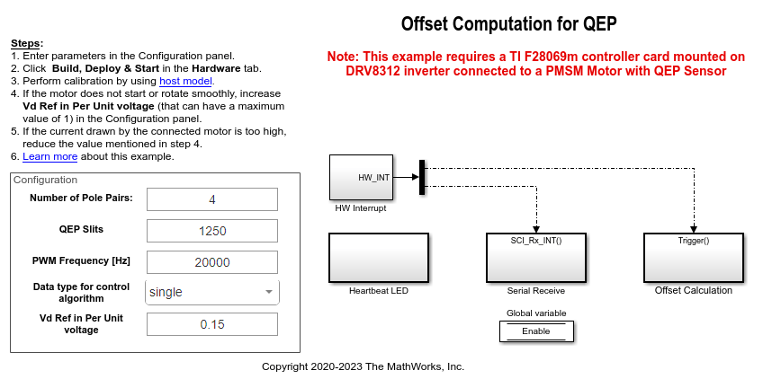
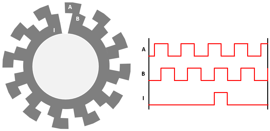
PMSM 的正交编码器偏移量校准
此示例计算转子的 d 轴与正交编码器检测到的编码器索引脉冲位置之间的偏移量。控制算法(在磁场定向控制和参数估计示例中可用)使用此偏移值来计算转子的 d 轴的精确位置。控制器需要此位置以在转子磁通参考系(d-q 参考系)中正确实现磁场定向控制 (FOC),从而正确运行永磁同步电机 (PMSM)。
使用正交编码器的 PMSM 磁场定向控制
此示例采用磁场定向控制 (FOC) 方法来控制三相永磁同步电机 (PMSM) 的转速。FOC 算法需要转子位置反馈,该反馈通过正交编码器获得。有关 FOC 的详细信息,请参阅磁场定向控制。

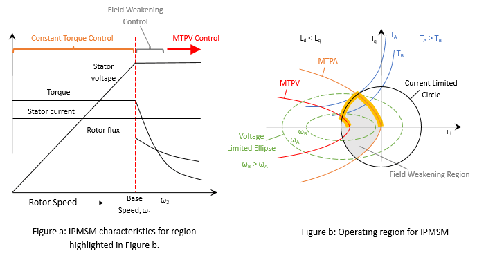
PMSM 的弱磁控制(使用 MTPA)
此示例采用磁场定向控制 (FOC) 方法来控制三相永磁同步电机 (PMSM) 的转矩和转速。FOC 算法需要转子位置反馈,该反馈通过正交编码器获得。有关 FOC 的详细信息,请参阅磁场定向控制。
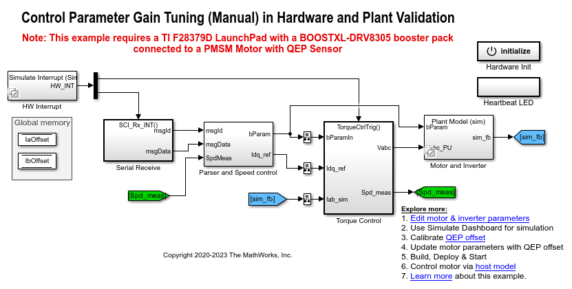
Tune Control Parameter Gains in Hardware and Validate Plant
Uses field-oriented control (FOC) to run a three-phase permanent magnet synchronous motor (PMSM) in different modes of operation for plant validation. FOC algorithm implementation needs the real-time feedback of the rotor position. This example uses a quadrature encoder sensor to measure the rotor position. For details about FOC, see 磁场定向控制.

使用 SI 单位的 PMSM 磁场定向控制
此示例采用磁场定向控制 (FOC) 方法来控制三相永磁同步电机 (PMSM) 的转速。然而,此示例中的 FOC 算法使用信号的 SI 单位来执行计算,而不使用数量的标幺表示(有关标幺制的详细信息,请参阅标幺制)。以下是信号及其 SI 单位:
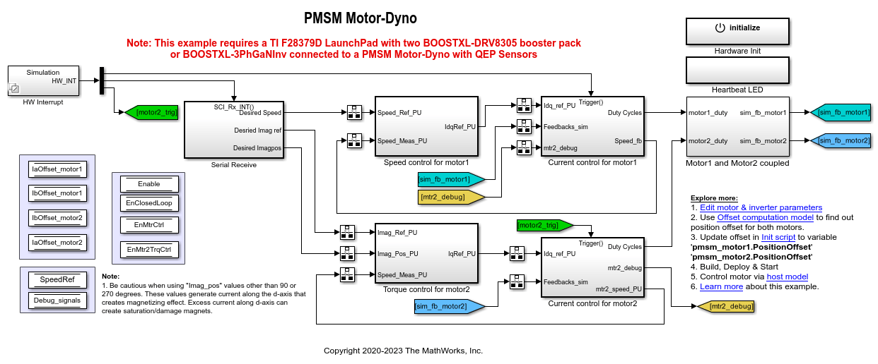
控制载有双电机(测功机)的 PMSM
此示例使用磁场定向控制 (FOC) 来控制测功机设置中耦合的两个三相永磁同步电机 (PMSM)。电机 1 在闭环转速控制模式下运行。电机 2 在转矩控制模式下运行,并且由于它们机械耦合,因此为电机 1 施加负载。您可以使用此示例在不同负载工况下测试电机。
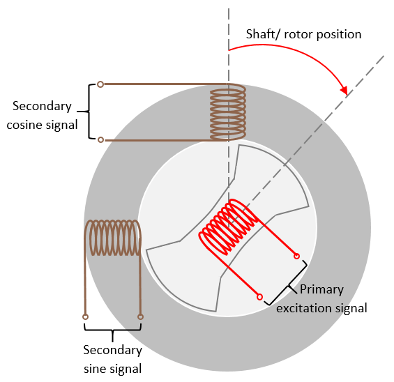
Monitor Resolver Using Serial Communication
Use the resolver sensor to measure the rotor position. The resolver consists of two stator (secondary) windings placed orthogonally around the resolver rotor (primary) winding. After you mount the resolver sensor over a PMSM, the resolver rotor winding rotates with the shaft of the running motor. Meanwhile, the controller provides a fixed-frequency excitation signal (alternating sinusoidal or square pulse) to the primary winding.
使用 Simscape Electrical 对逆变器中的开关动态特性进行建模
此示例使用磁场定向控制 (FOC) 来控制三相永磁同步电机 (PMSM) 的转速。它为您提供使用以下 Simscape™ Electrical™ 模块来代替 Motor Control Blockset™ 中 Average Value Inverter 模块的选项:
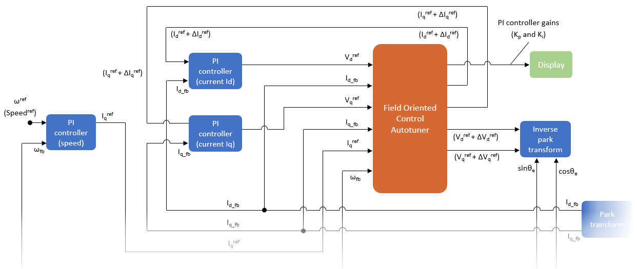
使用 Field Oriented Control Autotuner 调节 PI 控制器
此示例通过使用 Field Oriented Control Autotuner 模块计算转速和电流控制环中可用的 PI 控制器的增益值。有关此模块的详细信息,请参阅Field Oriented Control Autotuner。有关磁场定向控制的详细信息,请参阅磁场定向控制。
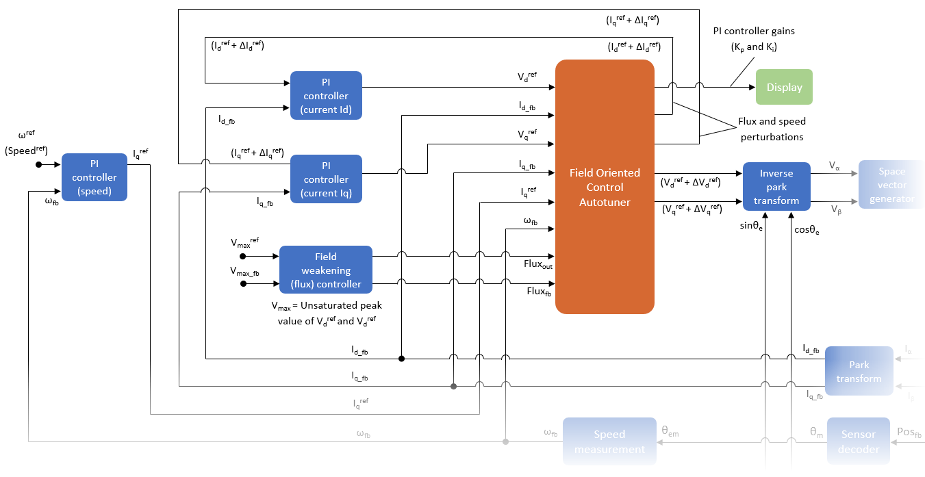
Tune PI Controllers (in Field-Weakening Control Mode) Using FOC Autotuner Block
Uses the Field Oriented Control Autotuner block to compute the gain values of the PI controllers available in the speed, current, and flux control loops of a field-weakening control algorithm. For details about this block, see Field Oriented Control Autotuner.
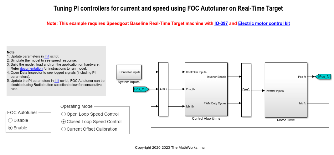
Tune PI Controllers Using Field Oriented Control Autotuner Block on Real-Time Systems
Compute the gain values of PI controllers within the speed and current controllers by using the Field Oriented Control Autotuner block.
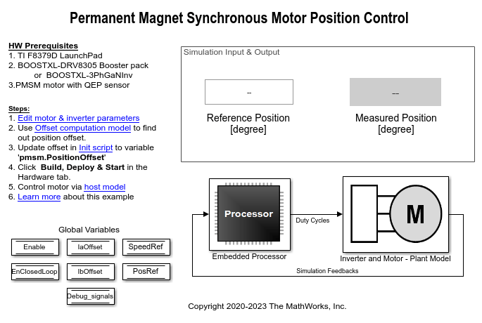
使用正交编码器实现 PMSM 的位置控制
此示例采用磁场定向控制 (FOC) 方法来控制三相永磁同步电机 (PMSM) 的位置。FOC 算法需要从正交编码器获得转子位置反馈。
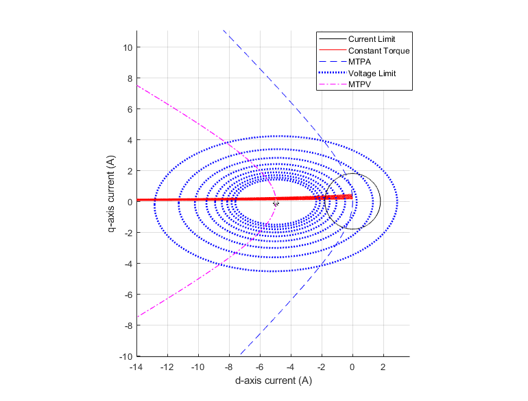
PMSM Drive Characteristics and Constraint Curves
Uses Motor Control Blockset™ to show how to use the PMSM characteristic plotting and PMSM milestone speed identification functions to obtain a control trajectory.
MATLAB Project for FOC of PMSM with Quadrature Encoder
This MATLAB® project provides a motor control example model that uses field-oriented control (FOC) to run a three-phase permanent magnet synchronous motor (PMSM) in different modes of operation. Implementing the FOC algorithm needs real-time rotor position feedback. This example uses a quadrature encoder sensor to measure the rotor position. For details about FOC, see 磁场定向控制.
Frequency Response Estimation of PMSM Using Field-Oriented Control
Performs frequency response estimation (FRE) of a plant model running a three-phase permanent magnet synchronous motor (PMSM). When you simulate or run the model on the target hardware, the model runs tests to estimate the frequency response as seen by each PI controller (also known as raw FRE data) and plots the FRE data to provide a graphical representation of the plant model dynamics.
Integrate MCU Scheduling and Peripherals in Motor Control Application
Identify and resolve issues with respect to peripheral settings and task scheduling early during development.

Partition Motor Control for Multiprocessor MCUs
Partition real-time motor control application on to multiple processors to achieve design modularity and improved control performance.
Estimate Initial Rotor Position Using Pulsating High-Frequency and Dual-Pulse Methods
Estimates the initial position (in electrical radians) of a stationary interior PMSM by using pulsating high-frequency (PHF) injection and dual pulse (DP) techniques.
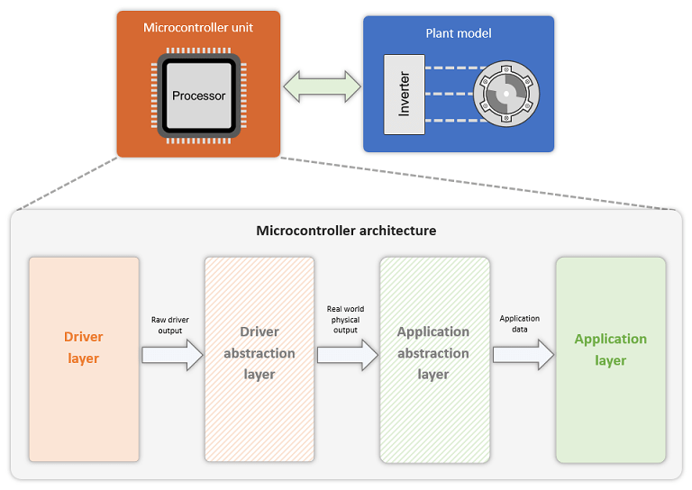
适用于自定义硬件的算法导出工作流
此示例说明如何使用任何自定义电机控制硬件(Motor Control Blockset™ 示例中未使用的硬件)运行使用磁场定向控制 (FOC) 的三相永磁同步电机 (PMSM)。使用算法导出工作流,涉及使用 Simulink® 和 Embedded Coder® 生成控制算法代码,然后将其与手动编写或外部生成的硬件驱动代码集成。此示例说明算法导出工作流以及中间步骤。

使用强化学习的 PMSM 磁场定向控制
此示例说明如何使用强化学习的控制设计方法来实现永磁同步电机 (PMSM) 的磁场定向控制 (FOC)。此示例使用 FOC 原理。不过,它使用强化学习 (RL) 智能体代替 PI 控制器。有关 FOC 的更多详细信息,请参阅磁场定向控制。
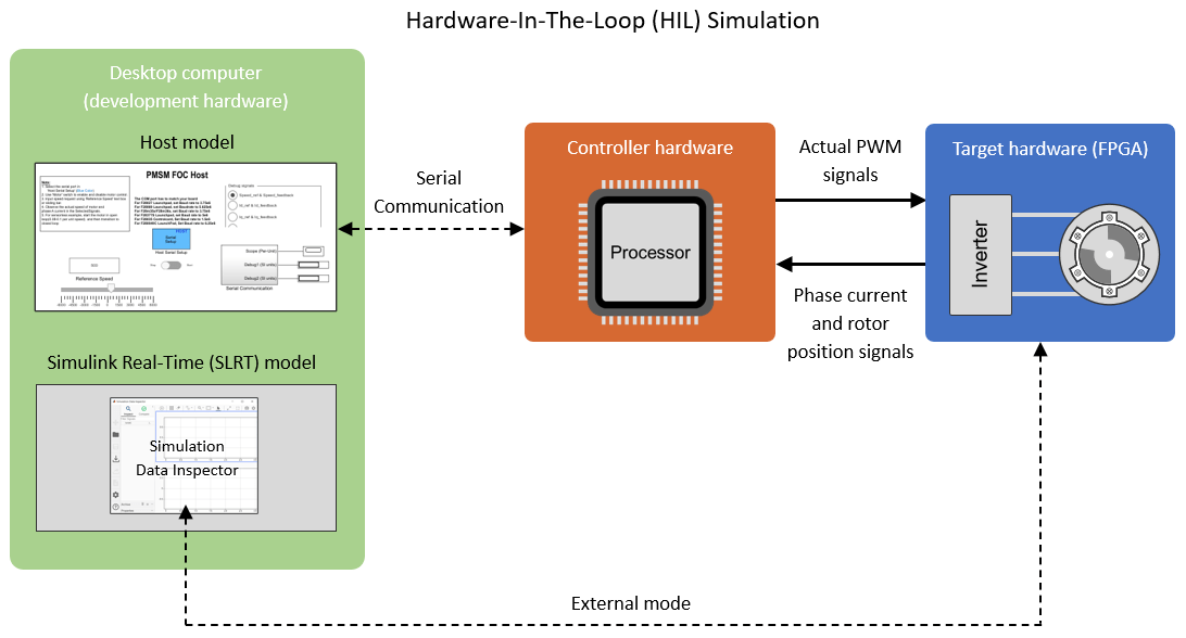
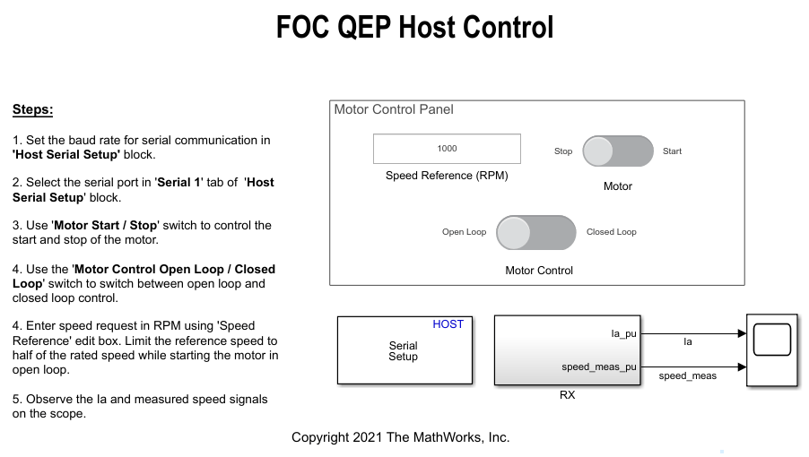
Field-Oriented Control (FOC) of PMSM Using Hardware-in-the-Loop (HIL) Simulation
Uses hardware-in-the-loop (HIL) simulation to implement the field-oriented control (FOC) algorithm to control the speed of a three-phase permanent magnet synchronous motor (PMSM). The FOC algorithm requires rotor position feedback, which is obtained by a quadrature encoder sensor. For more information on FOC, see 磁场定向控制.
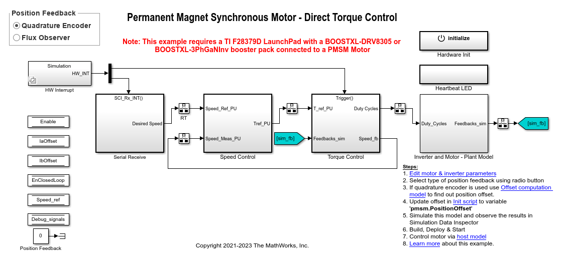
使用正交编码器或无传感器磁通观测器的 PMSM 直接转矩控制
此示例采用直接转矩控制 (DTC) 方法来控制三相永磁同步电机 (PMSM) 的转速。直接转矩控制 (DTC) 是一种矢量电机控制方法,它通过直接控制电机的磁通和转矩来实现电机转速控制。该示例算法需要从 PMSM 获取电机电流和位置反馈。它使用 DTC 的空间矢量脉冲宽度调制 (DTC-SVPWM) 变体,该变体使用空间矢量调制 (SVM) 来产生逆变器使用的脉冲宽度调制 (PWM) 占空比。有关此示例中使用的 DTC-SVPWM 算法的更多详细信息,请参阅直接转矩控制 (DTC)。
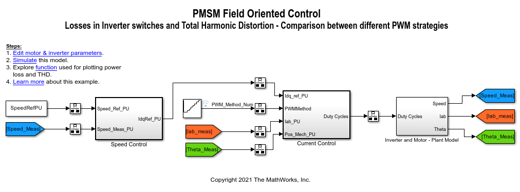
Determine Power Losses and THD for PWM Methods
Calculates the inverter power loss and total harmonic distortion (THD) in motor current for different pulse-width modulation (PWM) methods. The example uses field-oriented control (FOC) algorithm that runs a permanent-magnet synchronous motor (PMSM) in speed control mode as a reference. The example only supports simulation.
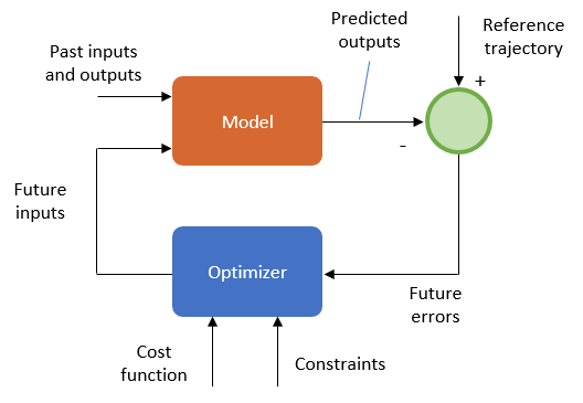
使用模型预测控制进行 PMSM 的磁场定向控制
此示例采用模型预测控制 (MPC) 技术来控制三相永磁同步电机 (PMSM) 的转速。
FOC of PMSM Using FPGA-Based Motor Control Development Kit
Use a Field-Oriented Control (FOC) algorithm for a Permanent Magnet Synchronous Motor (PMSM) by using blocks from the Motor Control Blockset™ on an FPGA device (Trenz Electronic™ Motor Control Development Kit TE0820).
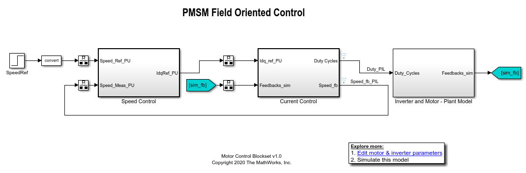
使用 PIL 测试进行代码验证和探查
此示例说明如何在 Texas Instruments® LAUNCHXL-F28379 硬件板上进行 PIL 探查。在处理器在环 (PIL) 仿真中,控制算法在目标硬件中执行,但被控对象模型在主机上运行。被控对象模型对控制器的输入和输出信号进行仿真,并使用串行通信接口与控制器通信。借助此功能,您可以使用 PIL 仿真来确定目标硬件上的执行时间,然后可以将其与主机上仿真模型的执行时间相比较。
Field-Weakening Control (with MTPA) of Nonlinear PMSM Using Lookup Table
Uses a lookup table (LUT) for a nonlinear permanent magnet synchronous motor (PMSM) and controller to run the motor using field-weakening control (with maximum torque per ampere (MTPA)). Use this example to replicate and run a finite element analysis (FEA) based nonlinear, high-fidelity PMSM in simulation. This example helps motor design engineers to simulate high-performance motors in real-world motor control applications. In addition, control system engineers can use this example to design control algorithms for a given set of motor parameter data to achieve high levels of accuracy in tracking and controlling speed and torque as well as to meet efficiency requirements, especially for high-performance motors.
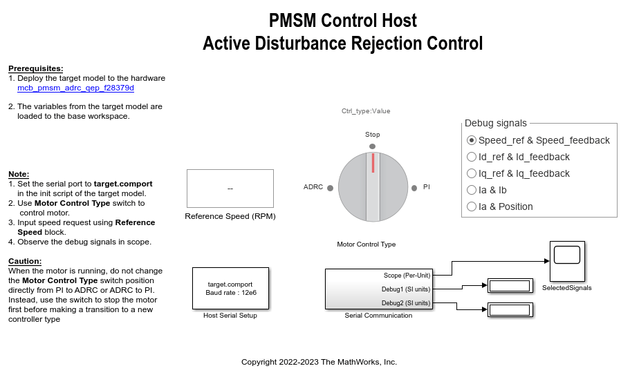
Implement PMSM Speed Control Using Active Disturbance Rejection Control
Implement active disturbance rejection control (ADRC) of the speed of a permanent magnet synchronous motor (PMSM) modeled in Simulink® using the Active Disturbance Rejection Control (Simulink Control Design) block. You can use the example to implement field-oriented control (FOC) using either a proportional integral (PI) or ADRC-based controller to run the motor in the speed control mode. Therefore, you can compare the performance of the PI and ADRC controllers.
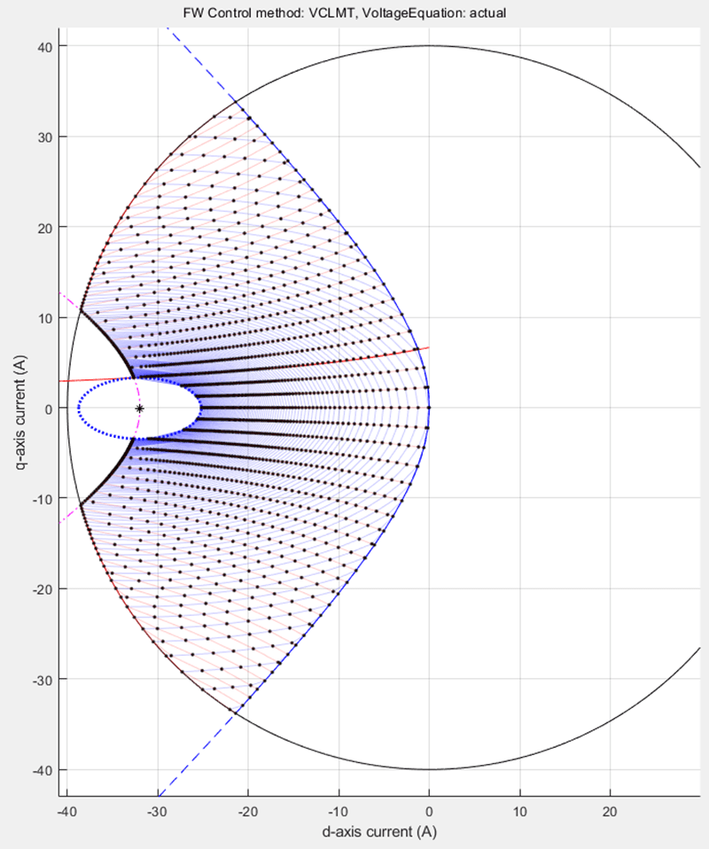
PMSM Constraint Curves and Their Application
Uses Motor Control Blockset™ to explain the fundamentals of constraint curves, utilization of these curves to determine operating currents, and usage of the grid of these currents in simulation or deployment environments.
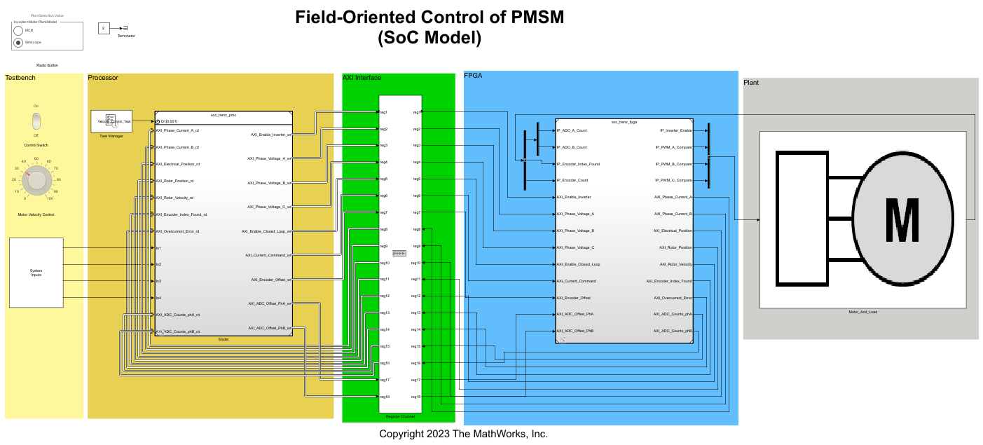
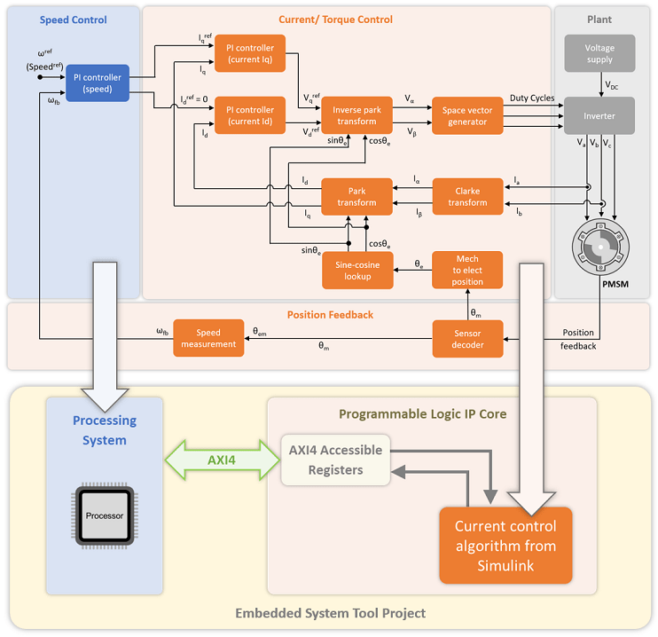
Implement Field-Oriented Control on FPGA SoC
Deploy a field-oriented control (FOC) algorithm for brushless DC motors to an SoC device by using a custom board target. A custom board target for the Trenz Electronic™ Motor Control Development Kit, based on Xilinx® Zynq® UltraScale+ MPSoC, allows you to deploy FOC application as a mix of software to the ARM® Cortex-A processor and hardware to the programmable logic of the device. This example uses the model and control algorithm partitioning from the Hardware-Software Partitioning of a Motor Control Algorithm (SoC Blockset) example.
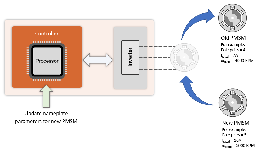
Swap Motors with Single Model Deployment of Sensor-Based FOC Algorithm
Run a permanent magnet synchronous motor (PMSM) in an industrial drive application setup using position-sensor-based field-oriented control (FOC). Industrial drives enable you to swap motors in real-time without repeated deployment of code. An industrial drive setup needs a fixed inverter and software that has the ability to adapt the control algorithm according to the new motor using only the updated nameplate parameters.
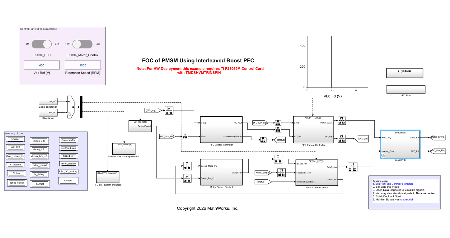
Field Oriented Control of PMSM Using Interleaved Boost Power Factor Correction
Implement field oriented control of PMSM with input power factor correction.
Swap Motors with Single Deployment of Sensorless FOC Algorithm
Run a permanent magnet synchronous motor (PMSM) in an industrial drive application setup using a sensorless field-oriented control (FOC) algorithm. The example uses a sensorless Flux Observer to estimate the motor position. Industrial drives enable you to replace a motor with a new one without repeated deployment of code. An industrial drive setup needs only nameplate parameters to adapt the software to the new motor.
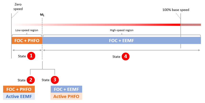
Initial Position Estimation and Field-Weakening Control of IPMSM Using Pulsating High-Frequency Injection and Extended EMF Observer
Uses sensorless techniques such as pulsating high-frequency injection and extended EMF observer to estimate and track motor position to run an interior permanent magnet synchronous motor (IPMSM) operation using field-weakening control (FWC).
Generate Motor Control Models for Selected Algorithm and Hardware
Use Motor Control Blockset™ to generate a Simulink® model that is configured for a specific hardware and motor control technique.
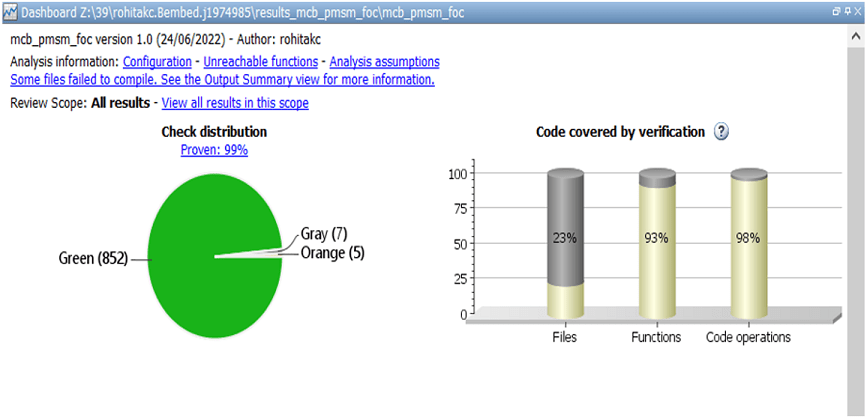
Analyze and Verify Motor Control Algorithms Using Polyspace
Uses the Polyspace® static code analysis tools to analyze and verify Simulink® models containing motor control algorithms. Static code analysis is a software verification technique that analyzes source code for quality, reliability, and security without executing the code. This approach uses robust error detection routines (that include checks for critical run-time errors) to identify bugs and defects and in addition ensures compliance with common coding standards. It provides a cost-effective alternative to measure and track the software quality metrics and eliminates the need to instrument the code or to write elaborate unit test cases.
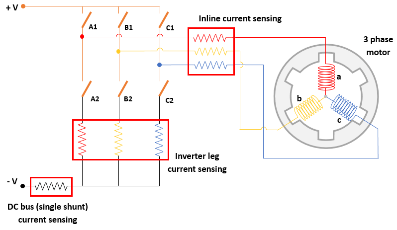
Sensorless Field-Oriented Control of PMSM Using DC Shunt Current Sensing
Implement sensorless field-oriented control (FOC) using only a single DC bus-based current measurement to run a permanent magnet synchronous motor (PMSM).
使用基于 I-F 控制的启动的 PMSM 无传感器磁场定向控制
此示例使用无传感器位置估计和基于 I-F 控制的启动来实现磁场定向控制 (FOC),以控制三相永磁同步电机 (PMSM) 的转速。

AUTOSAR-Based FOC of PMSM
Implement an AUTOSAR-based field-oriented control (FOC) algorithm to run a permanent magnet synchronous motor (PMSM).
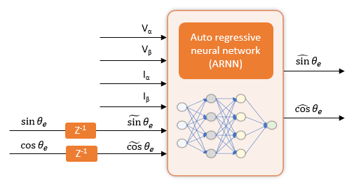
Field-Oriented Control of PMSM Using Position Estimated by Neural Network
Implement field-oriented control (FOC) of a permanent magnet synchronous motor (PMSM) using a rotor position estimated by an autoregressive neural network (ARNN) trained with Deep Learning Toolbox™.

六相 PMSM 的磁场定向控制
此示例说明如何使用磁场定向控制 (FOC) 来控制非对称六相永磁同步电机 (PMSM) 的转矩。
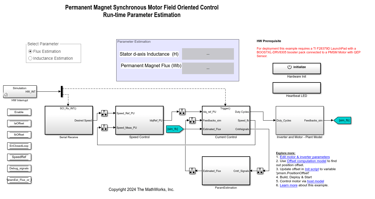
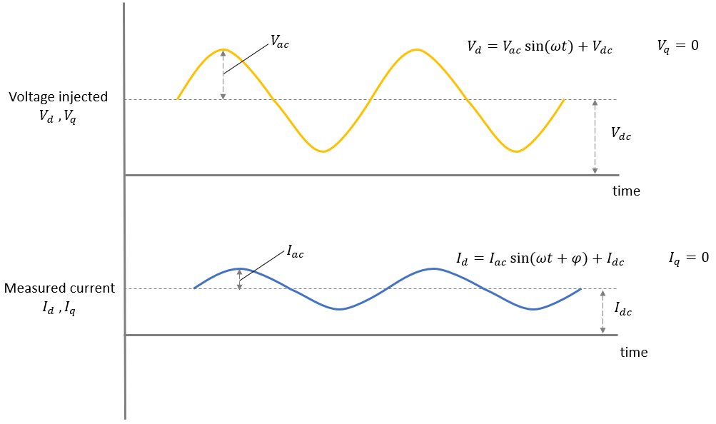
Run-Time Parameter Estimation of PMSM Using Sensor Feedback
Estimate the parameters of a permanent magnet synchronous motor (PMSM) at run-time. The example estimates the following PMSM parameters by running tests while the motor runs using a closed-loop field-oriented control (FOC) algorithm:
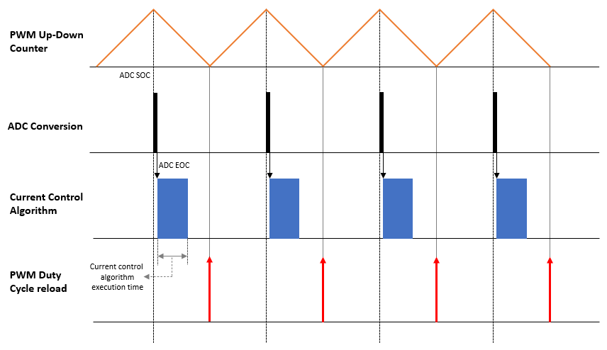
Motor Control Architectures Based on Different Current Sampling and PWM Frequencies
Enables you to implement different motor control architectures that use non-identical sampling rates for ADC conversion, PWM, and current controller algorithm to run a permanent magnet synchronous motor (PMSM) using field-oriented control (FOC).

Obtain Controller Gains to Run Motor Using Field-Oriented Control
Obtain PI controller gains using Optimum theory for the current control loop and speed control loop in Field Oriented Control (FOC) of a Permanent Magnet Synchronous Motor (PMSM). This example provides multiple options that you can use to obtain PI controller gains:
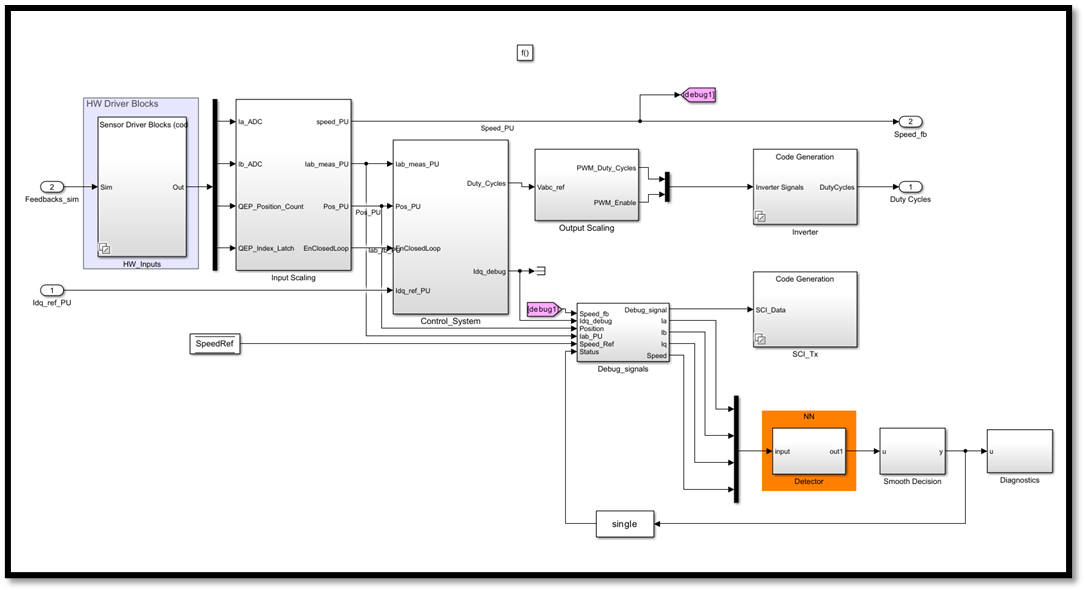
Detect Unbalanced Motor by Using Neural Network
Detect a mechanically unbalanced spinning motor by using a neural network (NN) developed using Deep Learning Toolbox™.